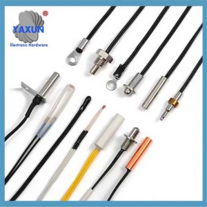
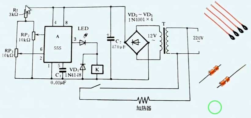
The wiring method of NTC (Отрицателен температурен коефициент) thermistor temperature sensor mainly depends on its application scenario and measurement requirements. The following is a common NTC temperature sensor connection method and matters that need to be noted when wiring:
1. Basic connection method
Pin identification:
Usually NTC temperature sensors have two or three pins.
Two pins are used to connect the power supply and the measurement circuit.
The third pin (if any) may be used for grounding or other special functions.
Power connection:
Connect the two main pins of the NTC temperature sensor to the positive and negative poles of the power supply, or to the input end of the measurement circuit.
Grounding treatment:
If the NTC temperature sensor has a ground pin, it should be connected to the ground end of the system to ensure the accuracy and safety of the measurement.
Series and parallel connection:
In some cases, it may be necessary to use a resistor in series with the NTC temperature sensor to form a voltage divider circuit to measure the change in the resistance value of the NTC temperature sensor.
The parallel connection method is to connect the NTC thermistor in parallel with other resistor devices to form a resistor voltage divider network, which is mainly used in temperature measurement or temperature compensation circuits.
The series connection method is to connect the NTC thermistor in series with other resistor devices to form a resistor voltage divider network, which is mainly used in temperature control circuits.
2. Precautions
Pin polarity:
When wiring, be sure to pay attention to the pin polarity of the NTC temperature sensor to ensure correct connection. If the pin is connected in reverse, it may cause measurement errors or damage the sensor.
Wire selection:
Wires with moderate length and uniform diameter should be selected for connection to reduce line impedance and signal loss.
The wire should have good insulation performance to avoid short circuit or leakage.
Температурен диапазон:
When selecting an NTC temperature sensor, consider whether its measurement range matches the actual application scenario.
When wiring, pay attention to the maximum operating temperature of the sensor to avoid exceeding its tolerance range.
Filtering and decoupling:
In some cases, it may be necessary to add filter capacitors or decoupling capacitors to the circuit to reduce noise interference and improve measurement accuracy.
Verification and calibration:
After the wiring is completed, the NTC temperature sensor should be verified and calibrated to ensure that its measurement is accurate and reliable. This usually requires the use of a standard temperature source or other measuring equipment for comparison and calibration.
Resistance matching:
Whether it is a parallel connection or a series connection, the wiring of the NTC thermistor must pay attention to the matching of the resistance value with other resistance devices to ensure the normal operation of the circuit.
Методът на свързване на сензора за температура на термистора NTC трябва да бъде определен съгласно действителния сценарий на приложението и изискванията за измерване. По време на процеса на окабеляване, Не забравяйте да обърнете внимание на полярността на щифта, Избор на проводник, температурен диапазон, филтриране и отделяне, заземяващо лечение, и проверка и калибриране, за да се гарантира точността и надеждността на измерването.
 English
 العربية
 Български
 粤语
粤语 中文(简体)
 中文(漢字)
 Nederlands
 Suomi
Suomi Français
 Deutsch
 Ελληνικά
 Magyar
 Italiano
 日本語
日本語 한국어
한국어 Polski
 Português
 Română
 Русский
 Slovenščina
 Español
 Svenska
 ภาษาไทย
 Türkçe
 Tiếng Việt


