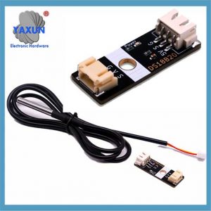
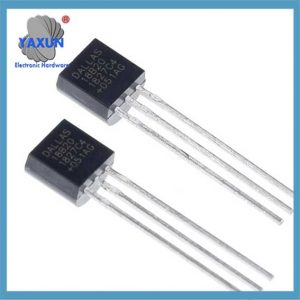
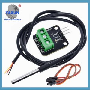
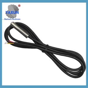
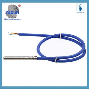
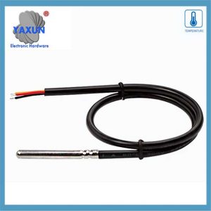
Wir bieten eine große Auswahl der besten 1-Wire DS18B20-Sensoranschlüsse, einschließlich Nanoflex, DisplayPort, USB, Solar, SATA, HDMI, Das ist eine Idee, SAS & viele mehr. Alle Kabel werden nach den höchsten Industriestandards hergestellt. Durch die Verwendung von Sensor Circuit Assembly für Box-Builds können Sie sich auf Ihr Design und Marketing konzentrieren, Kosten senken, und profitieren Sie von den Vorteilen unserer Montagelinien, QS-Prozesse, und Fertigungskompetenz.
Der DS18B20-Sensor kommuniziert über “1-Draht” Protokoll, Das bedeutet, dass für die gesamte Kommunikation mit einem Mikrocontroller eine einzige Datenleitung verwendet wird, Dadurch können mehrere Sensoren an dieselbe Leitung angeschlossen und anhand ihres eindeutigen 64-Bit-Seriencodes identifiziert werden; Diese einzelne Datenleitung wird mit einem Widerstand hochgezogen und der Sensor überträgt Daten, indem er die Leitung während bestimmter Zeitfenster auf niedrig zieht, um Informationsbits zu senden.
DS18B20 Temperatursensor: Die wasserdichte Sonde DS18B20 ist für den Unterwassereinsatz konzipiert, in der Lage, in nassen oder feuchten Umgebungen zu arbeiten, ohne durch Wasser oder Feuchtigkeit beschädigt zu werden.
Versorgungsspannung des Temperatursensors: 3.0V ~ 5,25 V;
Betriebstemperaturbereich:-55 ℃ zu +125 ℃ (-67 ℉ bis +257 ℉);
Bietet 9-Bit- bis 12-Bit-Celsius-Temperaturmessungen;
Das Adaptermodul ist mit einem Pull-up-Widerstand ausgestattet, und wird ohne externen Widerstand direkt mit dem GPIO des Raspberry Pi verbunden;
Verwenden Sie dieses Adaptermodul-Kit, um den Anschluss des wasserdichten Temperatursensors an Ihr Projekt zu vereinfachen.
1. Wichtige Punkte zum 1-Wire-Protokoll:
Einzelne Datenleitung:
Für die Kommunikation zwischen Sensor und Mikrocontroller ist nur ein Kabel erforderlich.
Halbduplex-Kommunikation:
Daten können in beide Richtungen gesendet werden, aber immer nur in eine Richtung.
Parasitenkraft:
Der DS18B20 kann während der Kommunikation direkt über die Datenleitung mit Strom versorgt werden, In einigen Fällen ist keine separate Stromversorgung erforderlich.
Eindeutige Geräteadressen:
Jeder DS18B20-Sensor verfügt über einen einzigartigen seriellen 64-Bit-Code, der es dem Mikrocontroller ermöglicht, einzelne Sensoren am Bus zu identifizieren und anzusprechen.
Kommunikationsschritte mit einem DS18B20:
1.1 Impuls zurücksetzen:
Der Mikrocontroller initiiert die Kommunikation, indem er die Datenleitung für eine bestimmte Dauer auf Low zieht (Reset-Impuls).
1.2 Präsenzpuls:
Wenn ein DS18B20 am Bus vorhanden ist, es antwortet mit einem kurzen Impuls, was auf seine Anwesenheit hinweist.
1.3 ROM-Befehl:
Der Mikrocontroller sendet einen ROM-Befehl, um entweder den eindeutigen 64-Bit-Code eines bestimmten Sensors zu lesen (“Match-ROM”) oder alle Sensoren am Bus anzusprechen (“ROM überspringen”).
1.4 Funktionsbefehl:
Abhängig von der gewünschten Operation (wie das Ablesen der Temperatur), Der Mikrocontroller sendet einen bestimmten Funktionsbefehl an den Sensor.
1.5 Datenübertragung:
Die Daten werden bitweise übertragen, wobei der Sensor die Datenleitung nach unten zieht, um a zu senden ‘0’ und die Leitung hoch gehen lassen, um eine „1“ zu senden.
2. Detaillierte Erläuterung des 1-Wire-Kommunikationsprotokolls von DS18B20
Der Grund, warum DS18B20 -Sensoren weit verbreitet sind – 1-Drahtkommunikationsprotokoll. Dieses Protokoll vereinfacht die Anforderungen an Hardwareverbindungen und bietet eine effiziente Möglichkeit, Daten zu übertragen. In diesem Kapitel wird der Arbeitsmechanismus und den Datenaustauschprozess des 1-Linie-Kommunikationsprotokolls zutiefst analysiert, um eine solide Grundlage für die nachfolgende Programmierpraxis zu legen.
2.1 Grundlagen des 1-Wire-Kommunikationsprotokolls
2.1.1 Merkmale des 1-Wire-Kommunikationsprotokolls:
DS18B20 1-Wire-Kommunikationsprotokoll wird ebenfalls genannt “Einzelbus” Technologie. Es hat die folgenden Funktionen: – Einzelbuskommunikation: Für die bidirektionale Datenübertragung wird nur eine Datenlinie verwendet, Dies reduziert die Komplexität der Verkabelung im Vergleich zu der traditionellen Mehrdrahtsensorkommunikationsmethode stark. – Multi-Device-Verbindung: Unterstützt das Verbinden mehrerer Geräte mit einem Datenbus, und identifiziert und kommuniziert durch Geräteidentifikationscodes. – Niedriger Stromverbrauch: Während der Kommunikation, Das Gerät kann sich in einem Standby-Zustand mit geringer Leistung befinden, wenn sie nicht an der Kommunikation teilnimmt. – Hohe Präzision: Mit einer kürzeren Datenübertragungszeit, Es kann externe Interferenzen reduzieren und die Datengenauigkeit verbessern.
2.1.2 Datenformat und Zeitanalyse der 1-Wire-Kommunikation
Das Datenformat des 1-Wire-Kommunikationsprotokolls folgt einer bestimmten Zeitregel. Es enthält das Initialisierungszeitpunkt, Schreiben Sie das Timing und lesen Sie das Timing:
Initialisierungszeitpunkt: Der Host beginnt zuerst das Timing für die Anwesenheitserkennung (Präsenzpuls) Durch den Bus für einen bestimmten Zeitraum hinunterziehen, und der Sensor sendet dann einen Vorhandenseinpuls als Antwort.
Timing schreiben: Wenn der Host ein Schreibzeitpunkt sendet, Es zieht zuerst den Bus runter für ungefähr 1-15 Mikrosekunde, Dann veröffentlicht der Bus, und der Sensor zieht den Bus herunter 60-120 Mikrosekunde reagiert.
Timing lesen: Der Host benachrichtigt den Sensor, Daten zu senden, indem er den Bus herunterzieht und veröffentlichen, und der Sensor gibt das Datenbit im Bus nach einer bestimmten Verzögerung aus.
2.2 Softwareimplementierung der Datenkommunikation
2.2.1 Initialisierung und Reset der 1-Leitungskommunikation
Auf Softwareebene, Das Initialisieren und Zurücksetzen der 1-Wire-Kommunikation ist der erste Schritt der Kommunikation. Das Folgende ist der Pseudocode zur Implementierung dieses Prozesses:
// OneWire-Kommunikationsinitialisierungsfunktion
void OneWire_Init() {
// Versetzen Sie den Bus in den Eingabemodus und aktivieren Sie den Pull-up-Widerstand
SetPinMode(DS18B20_PIN, INPUT_PULLUP);
// Warten Sie, bis der Bus frei ist
VerzögerungMikrosekunden(1);
// Senden Sie einen Reset-Impuls
OneWire_Reset();
}
// Funktion zum Zurücksetzen der OneWire-Kommunikation
OneWire_Reset ungültig machen() {
// Fahren Sie mit dem Bus herunter
SetPinMode(DS18B20_PIN, OUTPUT_LOW);
VerzögerungMikrosekunden(480);
// Geben Sie den Bus frei
SetPinMode(DS18B20_PIN, INPUT_PULLUP);
VerzögerungMikrosekunden(70);
// Warten Sie auf das Vorhandensein eines Impulses
Wenn (!WaitForOneWirePresence())
// Es wurde kein Puls festgestellt, Möglicherweise ist der Sensor nicht angeschlossen oder die Initialisierung ist fehlgeschlagen
HandleError();
VerzögerungMikrosekunden(410);
}
// Warten auf das Vorhandensein eines Pulses
bool WaitForOneWirePresence() {
Rückgabe von ReadPin(DS18B20_PIN) == 0; // Gehen Sie davon aus, dass bei niedrigem Pegel ein Signal vorhanden ist
}
2.2.2 Vorgänge zum Lesen und Schreiben von Daten
Datenlese- und -schreibvorgänge sind der Kernbestandteil der Sensorkommunikation. Der folgende Code zeigt, wie ein Byte auf einen Eindrahtbus geschrieben wird:
// Schreiben Sie ein Byte auf einen Eindrahtbus
void OneWire_WriteByte(Byte-Daten) {
für (int i = 0; ich < 8; i++) {
OneWire_WriteBit(Daten & 0x01);
Daten >>= 1;
}
}
// Schreiben Sie ein wenig auf einen Eindrahtbus
void OneWire_WriteBit(Bitdaten) {
SetPinMode(DS18B20_PIN, OUTPUT_LOW);
Wenn (Daten) {
// Geben Sie den Bus beim Schreiben frei 1
SetPinMode(DS18B20_PIN, INPUT_PULLUP);
VerzögerungMikrosekunden(1);
} anders {
// Ziehen Sie den Bus beim Schreiben weiterhin nach unten 0
VerzögerungMikrosekunden(60);
}
SetPinMode(DS18B20_PIN, INPUT_PULLUP);
VerzögerungMikrosekunden(1);
}
Als nächstes folgt die Funktion zum Lesen eines Bytes:
// Lesen Sie ein Byte vom Eindrahtbus
Byte OneWire_ReadByte() {
Bytedaten = 0;
für (int i = 0; ich < 8; i++) {
Daten >>= 1;
Wenn (OneWire_ReadBit())
Daten |= 0x80;
}
Daten zurückgeben;
}
// Lesen Sie ein wenig vom Eindrahtbus
Bit OneWire_ReadBit() {
SetPinMode(DS18B20_PIN, OUTPUT_LOW);
SetPinMode(DS18B20_PIN, INPUT_PULLUP);
VerzögerungMikrosekunden(3);
bool result = ReadPin(DS18B20_PIN);
VerzögerungMikrosekunden(57);
Ergebnis zurückgeben;
}
2.2.3 Überprüfungsmechanismus der OneWire-Kommunikation
Das OneWire-Kommunikationsprotokoll verwendet einen einfachen Verifizierungsmechanismus im Datenaustauschprozess, in der Regel durch Rücklesen der geschriebenen Daten, um die Richtigkeit der Daten zu überprüfen. Im Folgenden finden Sie einen Beispielcode zur Überprüfung der geschriebenen Daten:
Bytedaten = 0x55; // Gehen Sie davon aus, dass die Daten gesendet werden sollen
OneWire_WriteByte(Daten); // Daten auf den OneWire-Bus schreiben
Byte readData = OneWire_ReadByte(); // Daten vom OneWire-Bus zurücklesen
Wenn (readData != Daten) {
HandleError(); // Wenn die zurückgelesenen Daten nicht mit den geschriebenen Daten übereinstimmen, Behandeln Sie den Fehler
 English
 Afrikaans
 العربية
 বাংলা
বাংলা bosanski jezik
 Български
 Català
 粤语
粤语 中文(简体)
 中文(漢字)
 Hrvatski
 Čeština
 Nederlands
 Eesti keel
 Suomi
Suomi Français
 Deutsch
 Ελληνικά
 हिन्दी; हिंदी
 Magyar
 Bahasa Indonesia
 Italiano
 日本語
日本語 한국어
한국어 Latviešu valoda
 Lietuvių kalba
 македонски јазик
 Bahasa Melayu
 Norsk
Norsk پارسی
پارسی Polski
 Português
 Română
 Русский
 Cрпски језик
 Slovenčina
 Slovenščina
 Español
 Svenska
 ภาษาไทย
 Türkçe
 Українська
 اردو
اردو Tiếng Việt

