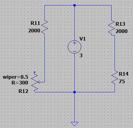
LTSpice simulation of 3-wire measurement scheme for PT100 (IDT) sensor: Pt100 is a thermal resistor temperature sensor, the full name is platinum resistor 100 ohmios. It is made of pure platinum, and its resistance value increases linearly in a certain proportion when the temperature changes.
PT100, el nombre completo de la resistencia térmica de platino, Es un sensor de temperatura resistivo hecho de platino. (punto), y su valor de resistencia cambia con la temperatura. El 100 después de PT significa que su valor de resistencia es 100 ohmios a 0 ℃, y su valor de resistencia es aproximadamente 138.5 ohmios a 100 ℃. It has the characteristics of high precision, buena estabilidad, fuerte capacidad antiinterferencia, and the relationship between its resistance and temperature change is: R=R0(1+αT), where α =0.00392, Ro is 100Ω (resistance value at 0℃), and T is Celsius temperature.
2. Import pt100 resistor
Since there is no pt100 in the LTspice component library, we need to import pt100 manually. Since the spice file of pt100 is not found, we import the sliding resistor here as a substitute. To import the sliding resistor, you need to add the following three files in the LTspice installation directory. Copy the three files (asc, asy and lib) separately, create files for each, and finally put them in the corresponding location of the LTSpice installation. Put asc with other schematics, put asy in sym under lib, and put lib in sub under lib. After adding, you can see potentiometer in the component in LTSpice. This potentiometer is the required sliding resistor.
potentiometer_test.asc
Version 4
SHEET 1 880 680
CABLE 272 48 0 48
CABLE 528 48 272 48
CABLE 272 80 272 48
CABLE 528 80 528 48
CABLE 0 96 0 48
CABLE 0 192 0 176
CABLE 272 208 272 176
CABLE 528 208 528 176
FLAG 272 208 0
FLAG 0 192 0
FLAG 320 128 out1
FLAG 528 208 0
FLAG 576 128 out2
SYMBOL voltage 0 80 R0
SYMATTR InstName V1
SYMATTR Value 10
SYMBOL potentiometer 272 176 M0
SYMATTR InstName U1
SYMATTR SpiceLine2 wiper=0.2
SYMBOL potentiometer 528 176 M0
SYMATTR InstName U2
SYMATTR SpiceLine R=1
SYMATTR SpiceLine2 wiper=0.8
TEXTO 140 228 Left 2 !.op
potentiometer.asy
Version 4
SymbolType BLOCK
LINE Normal 16 -31 -15 -16
LINE Normal -16 -48 16 -31
LINE Normal 16 -64 -16 -48
LINE Normal 1 -9 -15 -16
LINE Normal 1 0 1 -9
LINE Normal 1 -94 1 -87
LINE Normal -24 -56 -16 -48
LINE Normal -24 -40 -15 -48
LINE Normal -47 -48 -15 -48
LINE Normal -16 -80 16 -64
LINE Normal 1 -87 -16 -80
WINDOW 0 30 -90 Left 2
WINDOW 39 30 -50 Left 2
WINDOW 40 31 -23 Left 2
SYMATTR Prefix X
SYMATTR ModelFile potentiometer.lib
SYMATTR SpiceLine R=1k
SYMATTR SpiceLine2 wiper=0.5
SYMATTR Value2 potentiometer
PIN 0 -96 NONE 8
PINATTR PinName 1
PINATTR SpiceOrder 1
PIN 0 0 NONE 8
PINATTR PinName 2
PINATTR SpiceOrder 2
PIN -48 -48 NONE 8
PINATTR PinName 3
PINATTR SpiceOrder 3
potentiometer.lib
* This is the potentiometer
* _____
* 1–|_____|–2
* |
* 3
*
.SUBCKT potentiometer 1 2 3
.param w=limit(wiper,1metro,.999)
R0 1 3 {R*(1-w)}
R1 3 2 {R*(w)}
.ENDS
3. Wheatstone bridge to measure PT100 resistance
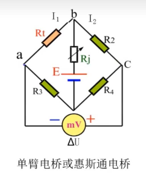
Conexión del puente de Wheatstone y modelo de simulación LTspice:
Cuando el puente está equilibrado, the voltage meter measurement value eq?%5CbigtriangleupU=0
I1*Rt=I2*R2
I1*R3=I2*R4
From this, it can be deduced that: Rt/R3=R2/R4
Eso es: Rt*R4=R2*R3
The resistance measurement result in this way has nothing to do with the accuracy of the voltage meter, the accuracy of the resistance, and the electromotive force. It avoids the error caused by the change of the power supply over time, and avoids the problem of ammeter voltage division, voltage meter shunt, and too many wire voltage division.
Different measurement methods of PT100:
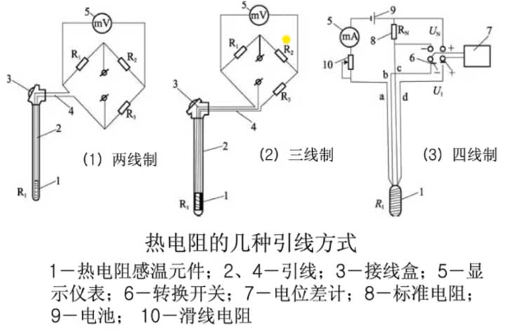
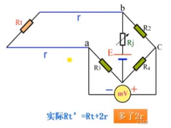
When the temperature point to be measured on site is far away from the instrument, it is necessary to connect the thermal resistor with a lead wire. The lead resistance is r. The two-wire system cannot avoid the error caused by the wire resistance during calculation, and the actual resistance value measured will be smaller.
In order to offset the error, a four-wire connection is introduced. When Rt increases by 2r, R2 also increases by 2r. No matter how long the wire is, the bridge can be balanced. Four wires need to be drawn. Since the voltages at points p and q are equal, they can be equivalent to one point, which is the three-wire connection method, eso es, the three-wire connection method simulated in this experiment. In practice, three-wire is also mostly used, taking into account both economy and accuracy.
4. Three-wire measurement LTSpice simulation
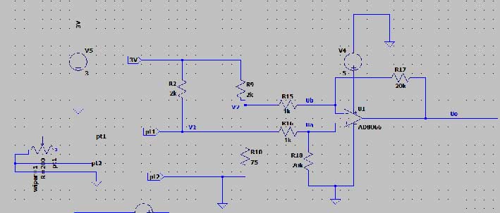
This experiment uses three-wire measurement, and connects the op amp circuit to the output part to amplify the output signal for easy measurement.
Uo= (V1-V2)*(R17/R15)=20*(V1-V2)
Eso es, V1=(Uo+20*V2)/20
According to the resistor voltage division:
V1 = Vs*(RT/(R2+Rt))
V2 = Vs*(R10/(R9+R10))
The input voltage of this simulation is 3V. After calculation, V2≈108.434mV
V1=(Uo+2168.68)/20
V1=Rt/(R7+Rpt) *3000
Entonces: Rt=2000V1/(3000-V1)
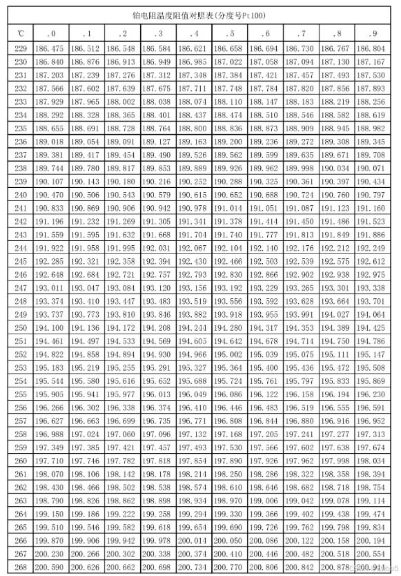
Rt is the corresponding resistance value of PT100. The corresponding temperature value can be obtained by looking up the table.
Set the resistance of the sliding rheostat (RT) a 130.6 ohms for the temperature of 78 grados Celsius, read V1, V2, and Uo to calculate Rt.
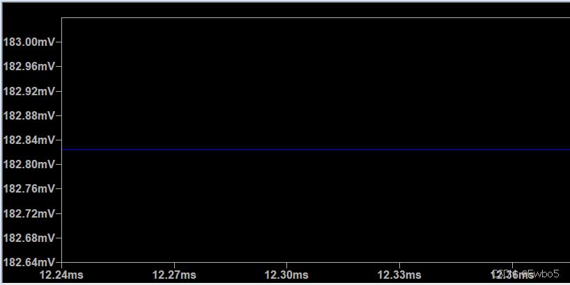
V1 is about 182.82mV, V2 is about 118.46mV, and U0 is about 1.39V. The calculated Rpt is about 129.78V. The table shows that the temperature read is 76 grados Celsius, which is close.
Set the resistance of the sliding rheostat (RT) a 200.05 ohms for the temperature of 266.5 grados Celsius, read V1, V2, and Uo to calculate Rt.
V1 is about 270.45mV, V2 is about 118.46mV, and U0 is about 3.0257V. The calculated Rpt is about 198.16V, and the error value is about 1%. The table shows that the temperature read is 261.3 grados Celsius, with an error of about 1%.
The temperature measurement principle of the three-wire PT100 is mainly based on the bridge method. The measurement circuit is usually an unbalanced bridge, and the PT100 is used as a bridge arm resistor of the bridge. When current passes through the PT100, the change in its resistance value will cause the change in the output voltage of the bridge. By measuring this output voltage, the resistance value of the PT100 can be calculated, and then the measured temperature can be obtained.
In order to eliminate the influence of lead resistance, the three-wire PT100 adopts a special design, connecting one wire to the power supply end of the bridge, and the other two wires are connected to the bridge arm where the PT100 is located and the bridge arm adjacent to it. De este modo, both bridge arms introduce lead resistances of the same resistance value, so that the bridge is in a balanced state. Por lo tanto, the change in lead resistance has no effect on the measurement result. Sin embargo, there will still be influences such as devices in actual measurement. The measured resistance value is not accurate. In order to eliminate this error, some compensation can be added when reading.
 English
 العربية
 Български
 粤语
粤语 中文(简体)
 中文(漢字)
 Nederlands
 Suomi
Suomi Français
 Deutsch
 Ελληνικά
 Magyar
 Italiano
 日本語
日本語 한국어
한국어 Polski
 Português
 Română
 Русский
 Slovenščina
 Español
 Svenska
 ภาษาไทย
 Türkçe
 Tiếng Việt

