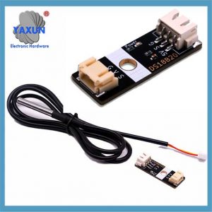
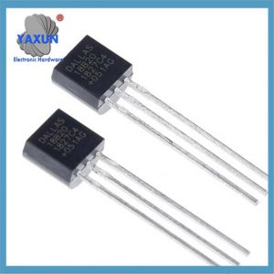
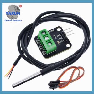
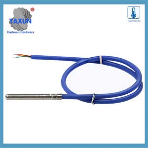
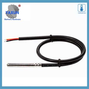
Ofrecemos una amplia gama de los mejores conectores de sensor DS18B20 de 1 cable, incluyendo Nanoflex, DisplayPort, USB, Solar, sata, hdmi, Esa es la idea, SAS & muchos más. Todos los cables se fabrican según los más altos estándares de la industria.. El uso del conjunto de circuitos de sensores para la construcción de cajas le permite centrarse en su diseño y marketing., reducir costos, y aproveche los beneficios de nuestras líneas de montaje, Procesos de control de calidad, y experiencia en fabricación.
El sensor DS18B20 se comunica mediante el “1-Cable” protocolo, lo que significa que utiliza una única línea de datos para todas las comunicaciones con un microcontrolador, permitiendo conectar múltiples sensores en la misma línea e identificarlos por su código de serie único de 64 bits; Esta única línea de datos se eleva con una resistencia y el sensor transmite datos bajando la línea durante intervalos de tiempo específicos para enviar bits de información..
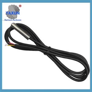
Sensor de temperatura DS18B20: La sonda impermeable DS18B20 está diseñada para uso bajo el agua., Capaz de operar en ambientes mojados o mojados sin ser dañado por el agua o la humedad..
Tensión de alimentación del sensor de temperatura: 3.0V ~ 5,25 V;
Rango de temperatura de funcionamiento:-55 ℃ +125 ℃ (-67 ℉ a +257 ℉);
Proporciona mediciones de temperatura Celsius de 9 bits a 12 bits;
El módulo adaptador está equipado con una resistencia pull-up, y se conecta directamente al GPIO de la Raspberry Pi sin resistencia externa;
Utilice este kit de módulo adaptador para simplificar la conexión del sensor de temperatura resistente al agua a su proyecto.
1. Puntos clave sobre el protocolo 1-Wire:
Línea de datos única:
Solo se necesita un cable para la comunicación entre el sensor y el microcontrolador..
Comunicación semidúplex:
Los datos se pueden enviar en ambas direcciones., pero solo una dirección a la vez.
poder parásito:
El DS18B20 se puede alimentar directamente desde la línea de datos durante la comunicación, eliminando la necesidad de una fuente de alimentación separada en algunos casos.
Direcciones de dispositivo únicas:
Cada sensor DS18B20 tiene un código de serie único de 64 bits que permite al microcontrolador identificar y direccionar sensores individuales en el bus..
Pasos de comunicación con un DS18B20:
1.1 Restablecer pulso:
El microcontrolador inicia la comunicación bajando la línea de datos durante un período específico. (restablecer el pulso).
1.2 Pulso de presencia:
Si hay un DS18B20 presente en el autobús, responderá con un pulso corto, indicando su presencia.
1.3 comando ROM:
El microcontrolador envía un comando ROM para leer el código único de 64 bits de un sensor específico (“ROM de partido”) o para abordar todos los sensores en el autobús (“Buque”).
1.4 Comando de función:
Dependiendo de la operación deseada (como leer la temperatura), El microcontrolador envía un comando de función específica al sensor..
1.5 Transferencia de datos:
Los datos se transmiten bit a bit., con el sensor bajando la línea de datos para enviar una ‘0’ y dejando que la línea suba alto para enviar un '1'.
2. Explicación detallada del protocolo de comunicación de 1 cable de DS18B20
La razón por la cual los sensores DS18B20 se usan ampliamente se debe en gran medida a su protocolo de comunicación único. – 1-Protocolo de comunicación de cables. Este protocolo simplifica los requisitos para las conexiones de hardware y proporciona una forma eficiente de transmitir datos. Este capítulo analizará profundamente el mecanismo de trabajo y el proceso de intercambio de datos del protocolo de comunicación de 1 línea para sentar una base sólida para la práctica de programación posterior..
2.1 Conceptos básicos del protocolo de comunicación de 1 cable
2.1.1 Características del protocolo de comunicación de 1 alambre:
El protocolo de comunicación DS18B20 1 alambre también se llama “autobús único” tecnología. Tiene las siguientes características: – Comunicación de autobuses individuales: Solo se utiliza una línea de datos para la transmisión de datos bidireccionales, lo que reduce en gran medida la complejidad del cableado en comparación con el método tradicional de comunicación del sensor de múltiples alambres.. – Conexión múltiple: Admite conectar múltiples dispositivos en un bus de datos, e identifica y se comunica a través de códigos de identificación del dispositivo. – Bajo consumo de energía: Durante la comunicación, El dispositivo puede estar en un estado de espera de baja potencia cuando no participa en la comunicación. – Alta precisión: Con un tiempo de transmisión de datos más corto, Puede reducir la interferencia externa y mejorar la precisión de los datos.
2.1.2 Formato de datos y análisis de tiempo de comunicación de 1 alambre
El formato de datos del protocolo de comunicación de 1 cable sigue una regla de tiempo específica. Incluye el tiempo de inicialización, Escribir tiempo y leer el tiempo:
Tiempo de inicialización: El huésped inicia la primera vez el tiempo de detección de presencia (Pulso de presencia) bajando por el autobús por un cierto período de tiempo, y el sensor luego envía un pulso de presencia en respuesta.
Escribir el tiempo: Cuando el anfitrión envía un tiempo de escritura, Primero baja el autobús por aproximadamente 1-15 microsegundos, Luego libera el autobús, y el sensor baja el autobús 60-120 microsegundos para responder.
Leer Tiempo: El host notifica que el sensor envía datos retirando el autobús y liberándolo, y el sensor emitirá la broca de datos en el bus después de un cierto retraso.
2.2 Implementación de software de comunicación de datos.
2.2.1 Inicialización y reinicio de comunicación de 1 línea.
A nivel de software, La inicialización y el restablecimiento de la comunicación 1-Wire es el primer paso de la comunicación.. El siguiente es el pseudocódigo para implementar este proceso.:
// Función de inicialización de comunicación OneWire
anular OneWire_Init() {
// Configure el bus en modo de entrada y habilite la resistencia pull-up
Establecer modoPin(DS18B20_PIN, ENTRADA_PULLUP);
// Espere a que el autobús esté inactivo
RetrasoMicrosegundos(1);
// Enviar un pulso de reinicio
OneWire_Reset();
}
// Función de reinicio de comunicación OneWire
anular OneWire_Reset() {
// Baja el autobús
Establecer modoPin(DS18B20_PIN, SALIDA_BAJA);
RetrasoMicrosegundos(480);
// Suelta el autobús
Establecer modoPin(DS18B20_PIN, ENTRADA_PULLUP);
RetrasoMicrosegundos(70);
// Espere la presencia de un pulso.
si (!Esperar la presencia de un cable())
// No se detectó pulso, tal vez el sensor no esté conectado o la inicialización falló
Error de manejo();
RetrasoMicrosegundos(410);
}
// Esperando la presencia de pulso.
bool WaitForOneWirePresence() {
volver LeerPin(DS18B20_PIN) == 0; // Supongamos que el nivel bajo es una presencia de señal.
}
2.2.2 Operaciones de lectura y escritura de datos.
Las operaciones de lectura y escritura de datos son la parte central de la comunicación del sensor.. El siguiente código muestra cómo escribir un byte en un bus de un solo cable.:
// Escribe un byte en un bus de un solo cable.
anular OneWire_WriteByte(datos de bytes) {
para (int yo = 0; i < 8; yo ++) {
OneWire_WriteBit(datos & 0x01);
datos >>= 1;
}
}
// Escribe un poco en un bus de un solo cable.
anular OneWire_WriteBit(datos de bits) {
Establecer modoPin(DS18B20_PIN, SALIDA_BAJA);
si (datos) {
// Suelta el bus al escribir 1
Establecer modoPin(DS18B20_PIN, ENTRADA_PULLUP);
RetrasoMicrosegundos(1);
} demás {
// Continúe bajando el autobús al escribir. 0
RetrasoMicrosegundos(60);
}
Establecer modoPin(DS18B20_PIN, ENTRADA_PULLUP);
RetrasoMicrosegundos(1);
}
La siguiente es la función para leer un byte.:
// Leer un byte del bus de un solo cable
byteOneWire_ReadByte() {
bytes de datos = 0;
para (int yo = 0; i < 8; yo ++) {
datos >>= 1;
si (OneWire_ReadBit())
datos |= 0x80;
}
devolver datos;
}
// Lea un poco del bus de un solo cable.
bit OneWire_ReadBit() {
Establecer modoPin(DS18B20_PIN, SALIDA_BAJA);
Establecer modoPin(DS18B20_PIN, ENTRADA_PULLUP);
RetrasoMicrosegundos(3);
resultado bool = ReadPin(DS18B20_PIN);
RetrasoMicrosegundos(57);
resultado de retorno;
}
2.2.3 Mecanismo de verificación de la comunicación OneWire
El protocolo de comunicación OneWire utiliza un mecanismo de verificación simple en el proceso de intercambio de datos., generalmente leyendo los datos escritos para verificar la exactitud de los datos. El siguiente es un código de muestra para verificar los datos escritos.:
bytes de datos = 0x55; // Supongamos que los datos a enviar
OneWire_WriteByte(datos); // Escribir datos en el bus OneWire
byte readData = OneWire_ReadByte(); // Leer datos del bus OneWire
si (leer datos != datos) {
Error de manejo(); // Si los datos leídos no coinciden con los datos escritos, manejar el error
 English
 Afrikaans
 العربية
 বাংলা
বাংলা bosanski jezik
 Български
 Català
 粤语
粤语 中文(简体)
 中文(漢字)
 Hrvatski
 Čeština
 Nederlands
 Eesti keel
 Suomi
Suomi Français
 Deutsch
 Ελληνικά
 हिन्दी; हिंदी
 Magyar
 Bahasa Indonesia
 Italiano
 日本語
日本語 한국어
한국어 Latviešu valoda
 Lietuvių kalba
 македонски јазик
 Bahasa Melayu
 Norsk
Norsk پارسی
پارسی Polski
 Português
 Română
 Русский
 Cрпски језик
 Slovenčina
 Slovenščina
 Español
 Svenska
 ภาษาไทย
 Türkçe
 Українська
 اردو
اردو Tiếng Việt

