Tuoteryhmät
Tuotetunnisteet
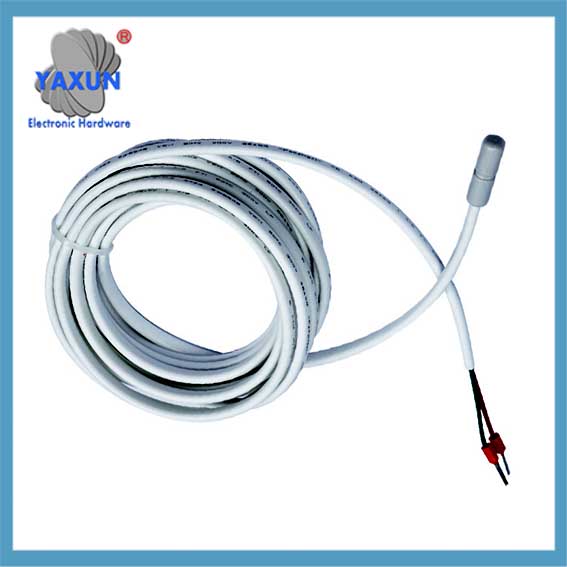
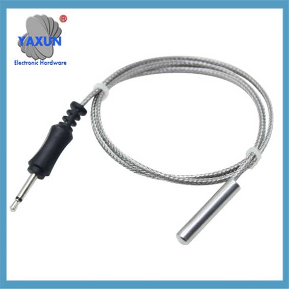
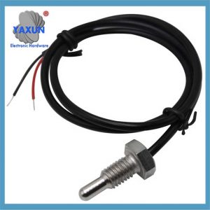
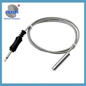
Kiinan mukautettu NTC-anturin anturi ja kaapeli
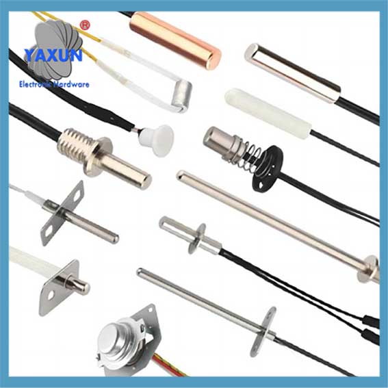
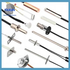
Kuten anturi, se on yleensä jaettu: NTC termistori anturi, PT100 anturi, PT1000 anturi, Ds18b20 anturi, veden lämpötila-anturi, autojen anturin anturi, RTD:n koetin, lämpötilan säätöanturi, lämpötilan säätöanturi, kodinkoneen anturin anturi, jne.
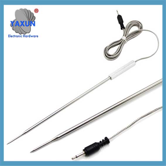
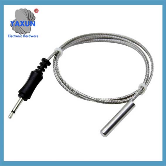
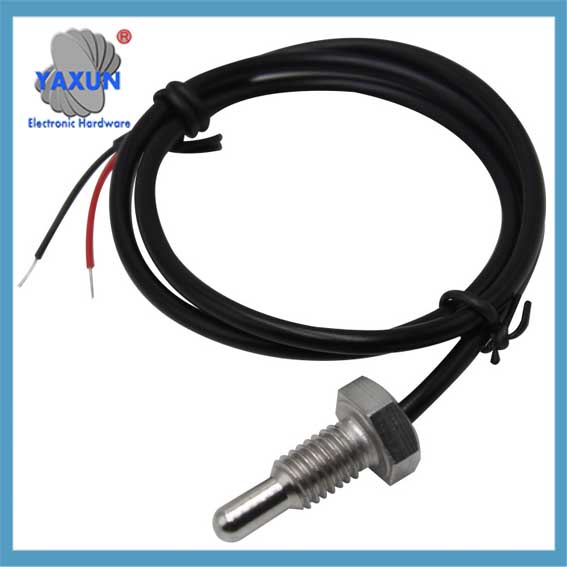
Anturin koetin ja kaapeli on anturin pakkausmuoto, joka on anturin perusyksikkö. Anturi on pakattu kohtuullisen elektronisen piirin ja ulkoisen pakkausrakenteen läpi. Siinä on joitain riippumattomia funktionaalisia komponentteja, joita tarvitsemme. Kuten anturi, se on yleensä jaettu: NTC termistori anturi, PT100 anturi, PT1000 anturi, Ds18b20 anturi, veden lämpötila-anturi, autojen anturin anturi, RTD:n koetin, lämpötilan säätöanturi, lämpötilan säätöanturi, kodinkoneen anturin anturi, jne.
NTC -koettimen rakenne, joka perustuu lämpötilan ennustamiseen ja sen lämpötilan mittausmenetelmään, koetin sisältää: useita NTC -koettimia; kuparikuori; metallitukirakenne, langan ja lämmönjohdin.
Askel 1, M NTC -koettimien joukossa, Hanki lämpötilat T0, T1, …, TN mitattuna samoin aikavälein kunkin NTC -koettimen läpi, missä n edustaa kerätyn lämpötilan sarjanumeroa;
Askel 2, Laske lämpötilaero VN = TNTN1, joka on kerätty vierekkäisiin lämpötilan mittausaikoihin;
Askel 3, Laske parametri α = VN/VN1;
Askel 4, Laske ennustettu lämpötila TP = TN1+VN/(1eräs) yhden koetin;
Askel 5, Laske mitattu lämpötila TB. Esillä oleva keksintö voi edelleen vähentää virhettä ja sillä on hyvä yleinen sovellettavuus.
Thermistorsin täydellinen analyysi!
🤔 Tiedätkö mitä termistori on? Se on pieni asiantuntija sähköisissä piireissä!
👍 termistorit, yksinkertaisesti, ovat tyyppisiä herkkiä elementtejä, jotka voivat säätää sen vastusarvoa lämpötilan muutosten mukaan.
🔥 Positiivinen lämpötilakerrointermistori (PTC), Kun lämpötila nousee, sen vastusarvo kasvaa merkittävästi. Tämä ominaisuus saa sen loistamaan automaattisissa ohjauspiireissä!
❄️ negatiivinen lämpötilakerroin termistori (NTC) on päinvastoin, vastus laskee lämpötilan noustessa. Kodinkoneissa, Sitä käytetään usein pehmeän alkuun, Automaattiset havaitsemis- ja ohjauspiirit.
💡 Nyt sinulla on syvempi käsitys termistorista! Elektronisessa maailmassa, Se on välttämätön rooli!
1. Johdanto NTC: hen
NTC -termistori on termistori, joka on nimetty negatiivisen lämpötilakertoimen lyhenteen mukaan. Yleensä, termi “termistori” viittaa NTC -termisreihin. Michael Faraday löysi sen, joka opiskeli tuolloin hopeasulfidipemonuktoreita, sisään 1833, ja kaupallistanut Samuel Ruuben 1930 -luvulla. NTC -termistori on mangaanista koostuva oksidi -puolijohde keraaminen (Mn), nikkeli (Sisä-) ja koboltti (Yhteistyö).
Se voidaan nähdä kaikkialla elämässämme. Johtuen ominaispiirteistä, että vastus vähenee lämpötilan noustessa, Sitä ei käytetä vain lämpötilan tunnistuslaitteena lämpömittarissa ja ilmastointilaitteissa, tai lämpötilanhallintalaite älypuhelimissa, Ketjut ja silitysraudat, mutta käytetään myös virransyöttölaitteiden nykyiseen hallintaan. Äskettäin, ajoneuvon sähköistyksen asteen kasvaessa, Autotuotteissa käytetään yhä enemmän termisejä.
2. Työperiaate
Yleensä, metallien kestävyys kasvaa lämpötilan noustessa. Tämä johtuu siitä, että lämpö vahvistaa hilan tärinää, ja vapaiden elektronien keskimääräinen liikkuvan nopeus vähenee vastaavasti.
Sitä vastoin, Vapaiden elektronien ja reikien osuus puolijohteissa kasvaa lämmönjohtavuuden vuoksi, ja tämä osa on suurempi kuin sen osan osuus, jossa nopeus pienenee, Joten vastusarvo laskee.
Lisäksi, Band -aukon olemassaolon vuoksi puolijohteissa, Kun ulkoisesti lämmitetään, Valenssikaistan elektronit siirtyvät johtamiskaistalle ja johtavat sähköä. Toisin sanoen, Resistanssi -arvo laskee lämpötilan noustessa.
3. Perusominaisuudet
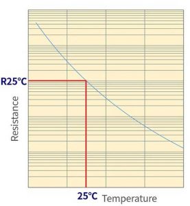
3.1 Resistenssi-lämpötilan ominaisuudet (R-T-ominaisuudet)
NTC-termistorin vastusarvo mitataan virralla, jolla on riittävän alhainen itsekämmitys (Lämpö, joka syntyy käytetyn virran takia). Vakiona, On suositeltavaa käyttää maksimaalista käyttövirtaa. Ja, Resistanssi -arvo on ilmaistava pareittain lämpötilan kanssa.
Ominaisuuskäyrä kuvataan seuraavalla kaavalla:
R0, R1: Kestävyysarvo lämpötilassa T0, T1
T0, T1: absoluuttinen lämpötila
B: B vakio
Kuva 1: NTC-termistorille ominaisuus R-T
3.2 B vakio
B -vakio on yksi arvo, joka karakterisoi NTC -termistoria. B -vakion säätäminen vaatii aina kaksi pistettä. B -vakio kuvaa kahden pisteen kaltevuutta.
Jos nämä kaksi pistettä ovat erilaisia, B -vakio on myös erilainen, Joten kiinnitä huomiota vertaamalla. (Katso luku 2)
Kuva 2: Erilaiset B -vakiot, jotka on valittu 2 piste
Tästä, Voidaan nähdä, että B on LNR: n rinte vs.. 1/T -käyrä:
Murata käyttää 25 ° C: ta ja 50 ° C: n määrittelemään B -vakio, kirjoitettu nimellä b (25/50).
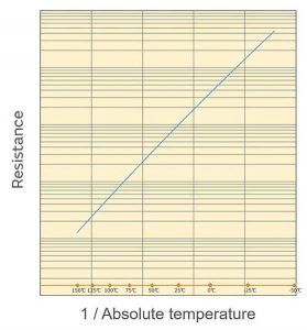
Kuten kuvassa on esitetty 3, 1/T (T on absoluuttinen lämpötila) on logaritmisessa suhteessa vastusarvoon. Voidaan nähdä, että suhde on lähellä suoraa linjaa.
Kuva 3: Lämpötilaominaisuudet, joiden vaakasuora akseli on 1/T
3.3 Volt-Amphere-ominaisuudet (V-I-ominaisuudet)
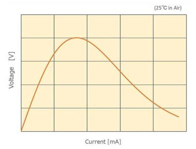
NTC-termistorien V-I-ominaisuudet on esitetty kuvassa 4.
Kuva 4: NTC-termistorien V-I-ominaisuudet
Alueella, jolla on matalavirta, Ohmisen kosketuksen jännite kasvaa vähitellen, kun virta kasvaa vähitellen. Virtavirtauksen aiheuttama itsemämmitys ei aiheuta vastuksen lämpötilan nousua hajottamalla lämpöä termistorin pinnalta ja muihin osiin.
kuitenkin, Kun lämmöntuotanto on suuri, Itse termistorin lämpötila nousee ja vastusarvo laskee. Sellaisella alueella, Virran ja jännitteen välinen suhteellinen suhde ei enää pidä.
Yleensä, termistoreita käytetään alueella, jolla itsekämmitys on mahdollisimman alhainen. Vakiona, On suositeltavaa, että toimintavirta pidetään suurimman käyttövirran alapuolella.
Jos sitä käytetään alueella, joka ylittää jännitteen huipun, Lämpökarkaiset reaktiot, kuten toistuva lämmitys ja vähentynyt vastus, aiheuttaen termistorin kääntymisen punaiseksi tai rikkoutumaan. Vältä sen käyttöä tällä alueella.
3.4 Lämpötilakeskinnan kerroin (eräs)
NTC -termistorin muutosnopeus lämpötilayksikköä kohti on lämpötilakerroin, joka lasketaan seuraavalla kaavalla.
Esimerkki: Kun lämpötila on lähellä 50 ° C ja B -vakio on 3380k
A = −3380/(273.15 + 50)² × 100 [%/°C] = −3,2 [%/°C]
Siksi, Lämpötilavastuskerroin on seuraava.
A = - b/t² × 100 [%/°C]
3.5 Lämpöhävitysvakio (d -d)
Kun ympäristön lämpötila on T1, Kun termistori kuluttaa Power P: tä (MW) ja sen lämpötila muuttuu T2: ksi, Seuraava kaava pitää kiinni.
P = D (T2 - T1)
Δ on lämpöhyytymisvakio (MW/° C). Yllä oleva kaava muutetaan seuraavasti.
d = p/ (T2 - T1)
Lämpöhäviövakio Δ viittaa lämpötilaan, joka tarvitaan lämpötilan nostamiseksi 1 ° C.
Lämpöhäviövakio δ määritetään tasapainon välillä “itsekämmitys virrankulutuksen vuoksi” ja “lämmön hajoaminen”, ja siksi vaihtelee merkittävästi termistorin toimintaympäristöstä riippuen.
Murata määritteli käsitteen “Lämpöhävitys vakio yksikköä kohti”.
3.6 Terminen aikavakio (T)
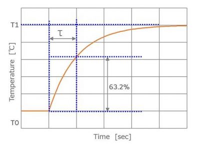
Kun lämpötilassa pidetty termistori muuttuu yhtäkkiä ympäristön lämpötilaan T1, Aika, joka kuluu vaihtamiseen kohderyhmään T1, kutsutaan lämpövakiona (T). Yleensä, Tämä arvo viittaa saavuttamiseen tarvittavaan aikaan 63.2% lämpötilaerosta T0: n ja T1: n välillä.
Kun termistori ylläpidetään yhdessä lämpötilassa (T0) altistuu toiselle lämpötilolle (T1), Lämpötila muuttuu eksponentiaalisesti, ja lämpötila (T) ajan kuluessa (t) ilmaistaan seuraavasti.
T = (T1 - T0) (1 - Exp (−T/T) ) + T0
Ota t = τ,
T = (T1 - T0) (1−1/e) + T0
(T - t0)/(T1 - T0) = 1 - 1/E = 0.632
Siksi τ määritetään ajankohtana 63.2% lämpötilaero.
Kuva 6: NTC -termistorin lämpöaikavakio
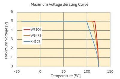
3.7 Enimmäisjännite (Vmax)
Suurin jännite, jota voidaan käyttää suoraan termistoriin. Kun käytetty jännite ylittää enimmäisjännitteen, Tuotteen suorituskyky huononee tai jopa tuhoutuu.
Lisäksi, Komponentin lämpötila nousee itsekämmityksen vuoksi. On tarpeen kiinnittää huomiota, että komponentin lämpötila ei ylitä käyttölämpötila -aluetta.
Kuva 7: NCU15 -tyypin enimmäisjännite
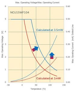
3.8 Enimmäiskäyttövirta (Silmukka), Enimmäisjännite (GTC)
Murata määrittelee suurimman käyttövirran ja maksimaalisen käyttöjännitteen virran ja jännitteenä, jolla itsekämmitys on 0,1 ℃, kun sitä käytetään. Tämän arvon perusteella, termistorit voivat saavuttaa tarkemman lämpötilan mittauksen.
Siksi, Virran/jännitteen asettaminen enimmäiskäyttövirran/jännitteen ylittäminen ei aiheuta termistorien suorituskyvyn heikkenemistä. kuitenkin, Huomaa, että komponentin itsekämmitys aiheuttaa havaitsemisvirheitä.
Kuinka Murata laskee maksimivirran
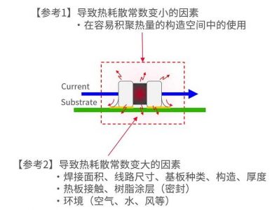
Laskettaessa enimmäiskäyttövirta, Lämpöhävitysvakio (1MW/° C) Yksikkökomponentin määrittelemä. Lämpöhäviövakio osoittaa lämmön hajoamisen asteen, Mutta lämmön hajoamistila vaihtelee suuresti työympäristöstä riippuen.
Työympäristö sisältää materiaalin, paksuus, rakenne, juotosalueen koko, keittolevy, hartsipakkaus, jne. substraatti. Yksikkökomponenttien määritelmän käyttö eliminoi ympäristöhäiriötekijöitä.
Kokemuksen mukaan, Lämpöhäviövakio todellisessa käytössä on kyse 3 kohtaan 4 kertaa yksikkökomponentin. Olettaen, että todellinen lämpöhäviövakio on 3.5 kertaa, Suurin käyttövirta on esitetty kuvassa olevassa sinisessä käyrässä. Verrattuna 1MW/° C: n tapaukseen, se on nyt 1.9 kertaa (√3.5 kertaa).
3.9 Nollakuormankestävyyden arvo
Virtastaalla mitattu vastusarvo (jännite) missä itsemuuntaminen on vähäistä. Vakiona, On suositeltavaa käyttää maksimaalista käyttövirtaa.
Kuva 9: Muratan vastusarvojen mittausmenetelmä
4. Kuinka käyttää
4.1 Piirikaavio
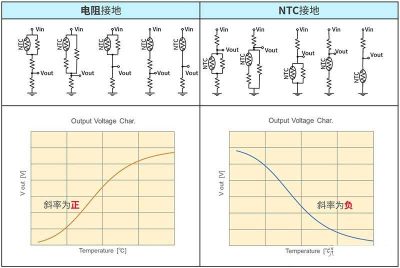
Lähtöjännite voi vaihdella NTC -termistorien johdotuskaaviosta riippuen. Voit simuloida sitä seuraavalla URL -osoitteella Murata -virallisella verkkosivustolla.
Simsurfing: NTC -termistorisimulaattori (Murata.co.jp)
Kuva 10 Vastuksen maadoitus- ja termistorien maadoituspiirien lähtöominaisuudet
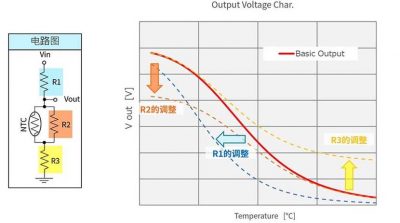
4.2 R1: n säätö (jännitteenjakajavastus), R2 (yhdensuuntainen vastus), R3 (sarjan vastus)
Lähtöjännite voi vaihdella piirikaavion mukaan.
Kuva 11 R -arvon ja lähtöominaisuuksien muutos
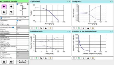
4.3 Tunnistusvirheen laskeminen Muratan virallisella työkalulla
Valitse NTC -termistorin asiaankuuluvat parametrit ja jännitteenjakopiirin asiaankuuluvat parametrit (Viitejännite ja jännitteenjakajavastus, vastustarkkuus), ja sitten lämpötilan havaitsemisen virhekäyrä voidaan tuottaa normaalisti, kuten alla olevassa kuvassa on esitetty:
Kuva 12 Lämpötilan havaitsemisvirhekäyrän luominen virallisilla työkaluilla
Ota yhteyttä
Sähköpostiasi odotellessa, vastaamme sinulle sisällä 12 tuntia arvokasta tietoa, jota tarvitset.
 English
 العربية
 Български
 粤语
粤语 中文(简体)
 中文(漢字)
 Nederlands
 Suomi
Suomi Français
 Deutsch
 Ελληνικά
 Magyar
 Italiano
 日本語
日本語 한국어
한국어 Polski
 Português
 Română
 Русский
 Slovenščina
 Español
 Svenska
 ภาษาไทย
 Türkçe
 Tiếng Việt
