catégories de produits
- Disjoncteur thermique 20
- Porte-boîte à fusibles 36
- Capteur de température 67
- Interrupteur thermique 64
- Fusible de voiture 19
- Fusibles boulonnés 7
- fusion thermique 32
- fusibles à montage en surface 12
- thermistance 22
- Porte-fusible à montage sur circuit imprimé 27
- Faisceau de câblage 6
- Porte-fusibles à lame 17
- thermostat 46
- Fusible électrique 14
Mots clés du produit
Messages récents
température de coupure du fusible thermique et du disjoncteur
Ils sont identiques dans la mesure où ils peuvent assurer une protection contre les courts-circuits. Le principe d'un fusible thermique est d'utiliser un courant circulant dans un conducteur pour provoquer son échauffement.. Lorsque le point de fusion du conducteur est atteint, le conducteur est fondu afin que les appareils électriques et les lignes protégés par le circuit ne soient pas brûlés.
Difference between thermal fuse (Panasonic, SWC, JK, RH) and circuit breaker:
Ils sont identiques dans la mesure où ils peuvent assurer une protection contre les courts-circuits. Le principe d'un fusible thermique est d'utiliser un courant circulant dans un conducteur pour provoquer son échauffement.. Lorsque le point de fusion du conducteur est atteint, le conducteur est fondu afin que les appareils électriques et les lignes protégés par le circuit ne soient pas brûlés. It is an accumulation of heat, so overload protection can also be achieved. Replace the melt as soon as it melts down.
The circuit breaker can also realize short circuit and overload protection of the line, but the principle is different. It realizes the open circuit protection by the current magnetic effect (electromagnetic trip), and the overload protection by the thermal effect of the current (not fused, it is not necessary to replace the device). Spécifiquement, in practice, when the electrical load in the circuit is close to the load of the fuse used for a long time, the fuse will gradually heat until it blows. As mentioned above, the blow of the fuse is the result of the combined effect of current and time to protect the line. It is one-time. The circuit breaker is a circuit in which the current suddenly increases, and when it exceeds the load of the circuit breaker, it will automatically open. It is a protection to the circuit for an instantaneous current increase, such as when the leakage is large, or when the short circuit, or the instantaneous current is large. When the cause is found out, it can be closed for continued use. As mentioned above, the blow of the thermal fuse is the result of the combined effect of current and time. The circuit breaker will trip as soon as the current exceeds its set value, and the role of time can be almost ignored. Circuit breakers are a common component in low-voltage power distribution. There are also places where thermal fuses are suitable.
Précautions
⑴ Notes on the use of thermal fuses:
① The protection characteristics of the thermal fuse should be compatible with the overload characteristics of the protected object. Considering the possible short-circuit current, select the fuse with corresponding breaking capacity.
② The rated voltage of the thermal fuse must be adapted to the line voltage level, and the rated current of the thermal fuse must be greater than or equal to the rated current of the melt.
③ The fuse rated currents of the thermal fuses at all levels in the line must be matched accordingly, and the rated current of the previous fuse must be greater than the rated current of the next fuse.
④ The fuse’s melt must use the matching melt as required. It is not allowed to increase the melt or replace the fuse with other conductors.
⑵ Thermal fuse inspection:
① Check whether the rated value of the thermal fuse and the melt matches the equipment to be protected.
② Check the appearance of the thermal fuse for damage and deformation, and for traces of flicker discharge on the porcelain insulation.
③ Check whether the contact points of the thermal fuse are intact, the contacts are tight, and there is no overheating.
④ Whether the fuse signal indicator of the thermal fuse is normal.
⑶ Use and maintenance of thermal fuse:
① When the fuser is blown, carefully analyze the cause of the blowout. The possible reasons are:
1) Short circuit or overload operation and normal fuse.
2) The hot melt has been used for too long, and the melt is erroneously broken due to oxidation or high temperature during operation.
3) There is mechanical damage during the installation of the hot melt, making its cross-sectional area smaller and causing misinterruption during operation.
② When dismantling the melt, the requirements are as follows:
1) Before installing a new melt, find out the cause of the melt failure. If the cause of the melt failure is not determined, do not disassemble and test the melt.
2) When replacing a new hot melt, check whether the rating of the melt matches the equipment being protected.
3) When replacing the new hot melt, check the internal burn of the fuse tube. If the burn is severe, replace the fuse tube at the same time. When the porcelain melting pipe is damaged, it is not allowed to replace it with other materials. Filler-type thermal fuses must be filled with filler when replacing the melt.

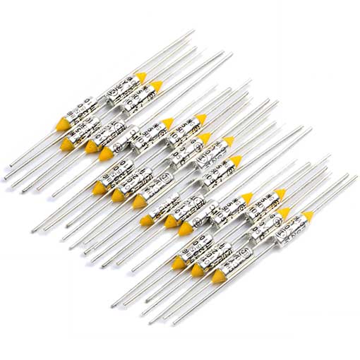
10Un fusible thermique 15A 20A 250V

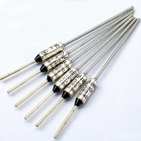
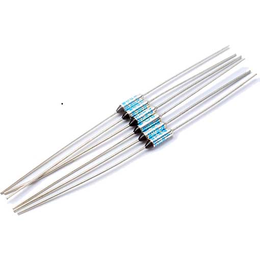
RH RY thermal fuse

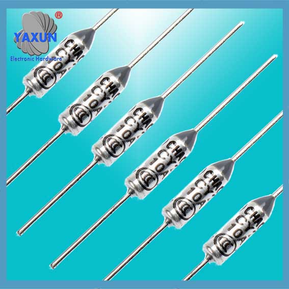
Panasonic thermal fuse
③ The thermal fuse should be maintained at the same time as the power distribution device:
1) Clean the dust and check the contact points.
2) Check the appearance of the thermal fuse (remove the fuse tube) for damage and deformation, and for flashing traces on the porcelain.
3) Check the thermal fuse, whether the fuse matches the protected circuit or equipment, and investigate if there is any problem.
4) Pay attention to the N line in the TN grounding system and the ground protection line of the equipment. The use of thermal fuses is not permitted.
5) Maintenance and inspection of the thermal fuse should be in accordance with the safety regulations, cut off the power supply, do not allow the thermal fuse tube to be removed with power on.
4. Thermal fuse adapter
Adapters for thermal fuses include a base, a micro-indicating switch, and a heat sink. The user can make the order in consultation with the thermal fuse manufacturer as required.
UN, the design and operating principle of thermal fuse
● Temperature fuse functional circuits to detect abnormal temperature and cut off. It can detect domestic or industrial heating temperature anomalies and electrical products quickly cu
t off the circuit can be achieved by preventing the effects of fire in unburned.
- Temperature fuse wire type with axial and radial lead type two. Use thermal particles (organic matter).
- Certification de sécurité: UL, ASC, VDE, BEBA, EPS, JET, CQC ... certificate, EU ROHS environmental directives
Deuxième, the application: thermal fuse to prevent overheating of the following areas - Product current: 1UN ,2UN , 3UN, 5UN, 10UN ,15UN, 20UN
Temperature fuse Brand: TAMURA, asseyez-vous, NEC, Émerson, LION, COLORANT, Panasonic, SWC, JK, RH
| Modèle | Rated operating temperature(Tf) | Actual operating temperature (Ct) | maintaining the temperature(Th) | limit temperature(Tm) | rated voltage (Ur) |
| DS28 | 95℃ | 91± 3 ℃ | 65℃ | 180℃ | 250V |
| DS21 | 102℃ | 98± 3 ℃ | 72℃ | 180℃ | 250V |
| DS04 | 115℃ | 110± 3 ℃ | 85℃ | 180℃ | 250V |
| DS06 | 125℃ | 121± 3 ℃ | 95℃ | 180℃ | 250V |
| DS07 | 130℃ | 125± 3 ℃ | 100℃ | 180℃ | 250V |
| DS08 | 135℃ | 131± 3 ℃ | 105℃ | 180℃ | 250V |
| DS09 | 145℃ | 141± 3 ℃ | 115℃ | 180℃ | 250V |
| DS10 | 150℃ | 145± 3 ℃ | 120℃ | 180℃ | 250V |
Contactez-nous
En attente de votre email, nous vous répondrons dans les 12 heures avec des informations précieuses dont vous aviez besoin.
 English
 العربية
 Български
 粤语
粤语 中文(简体)
 中文(漢字)
 Nederlands
 Suomi
Suomi Français
 Deutsch
 Ελληνικά
 Magyar
 Italiano
 日本語
日本語 한국어
한국어 Polski
 Português
 Română
 Русский
 Slovenščina
 Español
 Svenska
 ภาษาไทย
 Türkçe
 Tiếng Việt

