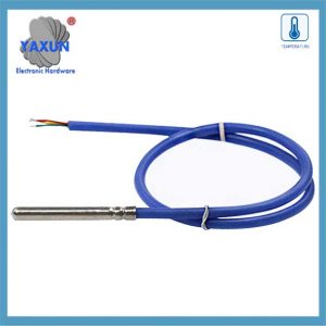
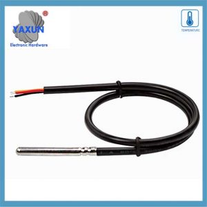
We offer a wide range of the best 1-Wire DS18B20 sensor connectors, including Nanoflex, DisplayPort, USB, Solar, SATA, HDMI, ATA IDE, SAS & many more. All cables are manufactured to the highest industry standards. Using Sensor Circuit Assembly for box builds allows you to focus on your design and marketing, reduce costs, and reap the benefits of our assembly lines, QA processes, and manufacturing expertise.
A DS18B20 érzékelő kommunikál a “1-Huzal” jegyzőkönyv, Ami azt jelenti, hogy egyetlen adatvonalat használ az összes kommunikációhoz a mikrovezérlővel, lehetővé téve több érzékelő csatlakoztatását ugyanabban a vonalon, és az egyedi 64 bites sorozatkóddal azonosítják; Ezt az egyetlen adatvonalat egy ellenállással magasan húzzák, és az érzékelő az adatokat továbbítja azáltal, hogy a vonalat az adott időrések során alacsonyan húzza, hogy biteket küldjön.
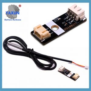
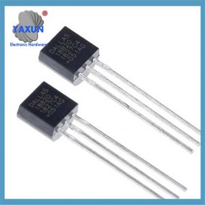
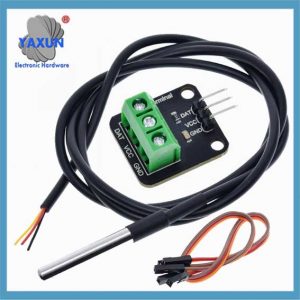
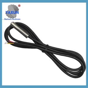
DS18B20 hőmérsékleti érzékelő: The DS18B20 waterproof probe is designed for underwater use, capable of operating in wet or moist environments without being damaged by water or moisture.
Temperature sensor supply voltage: 3.0V ~ 5.25V;
Üzemi hőmérsékleti tartomány:-55 ℃ +125 ℃ (-67 ℉ to +257 ℉);
Provides from 9-bit to 12-bit Celsius temperature measurements;
Adapter module is equipped with a pull-up resistor, and directly connects to the GPIO of the Raspberry Pi without an external resistor;
Use this adapter module kit to simplify connecting the waterproof temperature sensor to your project.
1. Key points about the 1-Wire protocol:
Single data line:
Only one wire is needed for communication between the sensor and the microcontroller.
Half-duplex communication:
Data can be sent in both directions, but only one direction at a time.
Parasite power:
The DS18B20 can be powered directly from the data line during communication, eliminating the need for a separate power supply in some cases.
Unique device addresses:
Each DS18B20 sensor has a unique 64-bit serial code that allows the microcontroller to identify and address individual sensors on the bus.
Communication steps with a DS18B20:
1.1 Reset pulse:
The microcontroller initiates communication by pulling the data line low for a specific duration (reset pulse).
1.2 Presence pulse:
If a DS18B20 is present on the bus, it will respond with a short pulse, indicating its presence.
1.3 ROM command:
The microcontroller sends a ROM command to either read the unique 64-bit code of a specific sensor (“Match ROM”) or to address all sensors on the bus (“Skip ROM”).
1.4 Function command:
Depending on the desired operation (like reading temperature), the microcontroller sends a specific function command to the sensor.
1.5 Data transfer:
Data is transmitted bit-by-bit, with the sensor pulling the data line low to send a ‘0’ and letting the line go high to send a ‘1’.
2. A DS18B20 1 vezetékes kommunikációs protokolljának részletes magyarázata
A DS18B20 érzékelőket széles körben használják, nagyrészt az egyedi kommunikációs protokoll miatt – 1-Vezetékes kommunikációs protokoll. Ez a protokoll leegyszerűsíti a hardver kapcsolatokra vonatkozó követelményeket, és hatékony módszert kínál az adatok továbbítására. Ez a fejezet mélyen elemzi az 1-vonalú kommunikációs protokoll működési mechanizmusát és adatcsere-folyamatát, hogy szilárd alapot teremtsen a későbbi programozási gyakorlathoz.
2.1 Az 1 vezetékes kommunikációs protokoll alapjai
2.1.1 Az 1 vezetékes kommunikációs protokoll jellemzői:
A DS18B20 1 vezetékes kommunikációs protokollt is nevezik “egyetlen busz” technológia. A következő funkciókkal rendelkezik: – Egyetlen buszos kommunikáció: Csak egy adatvonalat használnak a kétirányú adatátvitelhez, ami nagymértékben csökkenti a vezetékek bonyolultságát a hagyományos többvezetékes érzékelő kommunikációs módszerhez képest. – Több eszköz csatlakozás: Támogatja a több eszköz csatlakoztatását egy adatbuszon, és azonosítja és kommunikál az eszköz azonosítási kódjain keresztül. – Alacsony energiafogyasztás: A kommunikáció alatt, Az eszköz alacsony teljesítményű készenléti állapotban lehet, ha nem vesz részt a kommunikációban. – Nagy pontosságú: Rövidebb adatátviteli idővel, Csökkentheti a külső interferenciát és javíthatja az adatok pontosságát.
2.1.2 Adatformátum és időzítési elemzés az 1 vezetékes kommunikációról
Az 1 vezetékes kommunikációs protokoll adatformátuma egy adott időzítési szabályt követi. Ez magában foglalja az inicializálás időzítését, Írja be az időzítést és olvassa el az időzítést:
Inicializálás időzítés: A gazdagép először elindítja a jelenlét -észlelési időzítést (Jelenléti impulzus) azáltal, hogy egy bizonyos ideig lehúzza a buszt, és az érzékelő ezután válaszként jelenik meg egy jelenléti pulzusot.
Írja meg az időzítést: Amikor a gazdagép írási időzítést küld, Először kb. 1-15 mikroszekundum, Ezután elengedi a buszt, És az érzékelő behúzza a buszt 60-120 mikrosekundumok a reagáláshoz.
Olvassa el az időzítést: A gazdagép értesíti az érzékelőt, hogy küldjön adatokat a busz lehúzásával és elengedésével, És az érzékelő egy bizonyos késleltetés után adja ki az adatot a buszon.
2.2 Software implementation of data communication
2.2.1 Initialization and reset of 1-line communication
At the software level, initialization and reset of 1-Wire communication is the first step of communication. The following is the pseudo code to implement this process:
// OneWire communication initialization function
void OneWire_Init() {
// Set the bus to input mode and enable the pull-up resistor
SetPinMode(DS18B20_PIN, INPUT_PULLUP);
// Wait for the bus to be idle
DelayMicroseconds(1);
// Send a reset pulse
OneWire_Reset();
}
// OneWire communication reset function
void OneWire_Reset() {
// Pull down the bus
SetPinMode(DS18B20_PIN, OUTPUT_LOW);
DelayMicroseconds(480);
// Release the bus
SetPinMode(DS18B20_PIN, INPUT_PULLUP);
DelayMicroseconds(70);
// Wait for the presence of a pulse
ha (!WaitForOneWirePresence())
// No pulse was detected, maybe the sensor is not connected or the initialization failed
HandleError();
DelayMicroseconds(410);
}
// Waiting for the presence of a pulse
bool WaitForOneWirePresence() {
return ReadPin(DS18B20_PIN) == 0; // Assume low level is a signal presence
}
2.2.2 Data reading and writing operations
Data reading and writing operations are the core part of sensor communication. The following code shows how to write a byte to a one-wire bus:
// Write a byte to a one-wire bus
void OneWire_WriteByte(byte data) {
for (int i = 0; i < 8; i++) {
OneWire_WriteBit(adat & 0x01);
adat >>= 1;
}
}
// Write a bit to a one-wire bus
void OneWire_WriteBit(bit data) {
SetPinMode(DS18B20_PIN, OUTPUT_LOW);
ha (adat) {
// Release the bus when writing 1
SetPinMode(DS18B20_PIN, INPUT_PULLUP);
DelayMicroseconds(1);
} más {
// Continue to pull the bus low when writing 0
DelayMicroseconds(60);
}
SetPinMode(DS18B20_PIN, INPUT_PULLUP);
DelayMicroseconds(1);
}
Next is the function to read a byte:
// Read a byte from the one-wire bus
byte OneWire_ReadByte() {
byte data = 0;
for (int i = 0; i < 8; i++) {
adat >>= 1;
ha (OneWire_ReadBit())
adat |= 0x80;
}
return data;
}
// Read a bit from the one-wire bus
bit OneWire_ReadBit() {
SetPinMode(DS18B20_PIN, OUTPUT_LOW);
SetPinMode(DS18B20_PIN, INPUT_PULLUP);
DelayMicroseconds(3);
bool result = ReadPin(DS18B20_PIN);
DelayMicroseconds(57);
return result;
}
2.2.3 Verification mechanism of OneWire communication
The OneWire communication protocol uses a simple verification mechanism in the data exchange process, usually by reading back the written data to verify the correctness of the data. The following is a sample code for verifying the written data:
byte data = 0x55; // Assume that the data to be sent
OneWire_WriteByte(adat); // Write data to the OneWire bus
byte readData = OneWire_ReadByte(); // Read back data from the OneWire bus
ha (readData != data) {
HandleError(); // If the read-back data does not match the written data, handle the error
 English
 العربية
 Български
 粤语
粤语 中文(简体)
 中文(漢字)
 Nederlands
 Suomi
Suomi Français
 Deutsch
 Ελληνικά
 Magyar
 Italiano
 日本語
日本語 한국어
한국어 Polski
 Português
 Română
 Русский
 Slovenščina
 Español
 Svenska
 ภาษาไทย
 Türkçe
 Tiếng Việt

