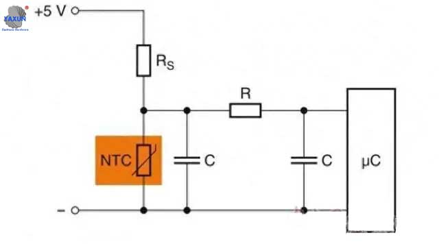
NTC thermistor Sensor temperature measurement circuit diagram
The temperature measurement circuit uses an op amp in a non–inverting configuration with inverting reference to offset and gain the signal, which helps to utilize the full ADC resolution and increase measurement accuracy. In order to ensure the normal operation of power semiconductor components, logic components, microcontrollers and processors, overheating must be avoided as much as possible. With compact size (such as EIA0402), the new SMD NTC thermistor can be placed directly near the microcontroller and other hot spots on the circuit board. Because the solder joints can form good thermal contact with the circuit board, and the self-heating of the components is minimal. Ezért, the new thermistor can perform high-precision temperature monitoring of sensitive semiconductor components. Due to the extremely high thermal shock resistance of EPCOS SMDNTC thermistors, this series of thermistors is not only suitable for reflow soldering processes, but also for wave soldering. Designers can place the thermistor on the bottom of the circuit board, such as the back of the microcontroller, to ensure that even large-sized microcontrollers can form excellent thermal contact. The figure below shows a typical microcontroller protection circuit.
NTC Temperature sensing with NTC Circuit Design Description
This temperature sensing circuit uses a resistor in series with a negative–temperature–coefficient (NTC) thermistor to form a voltage divider, which has the effect of producing an output voltage that is linear over temperature. The circuit uses an op amp in a non–inverting configuration with inverting reference to offset and gain the signal, which helps to utilize the full ADC resolution and increase measurement accuracy.
Design Notes
1. Use the op amp in a linear operating region. Linear output swing is usually specified under the AOL test conditions. TLV9002 linear output swing 0.05 V to 3.25 V.
2. The connection, Vin, is a positive temperature coefficient output voltage. To correct a negative temperature coefficient (NTC) output voltage, switch the position of R1 and the NTC thermistor.
3. Choose R1 based on the temperature range and the value of NTC.
4. Using high value resistors can degrade the phase margin of the amplifier and introduce additional noise in the circuit. It is recommended to use resistor values around 10 kΩ or less.
5. A capacitor placed in parallel with the feedback resistor will limit bandwidth, improve stability and help reduce noise
NTC thermistor temperature measurement circuit diagram (én)
In order to ensure the normal operation of power semiconductor components, logic components, microcontrollers and processors, overheating must be avoided as much as possible. With compact size (such as EIA0402), the new SMDNTC thermistor can be placed directly near the microcontroller and other hot spots on the circuit board. Because the solder joints can form good thermal contact with the circuit board, and the self-heating of the components is minimal. Ezért, the new thermistor can perform high-precision temperature monitoring of sensitive semiconductor components. Due to the extremely high thermal shock resistance of EPCOS SMDNTC thermistors, this series of thermistors is not only suitable for reflow soldering processes, but also for wave soldering. Designers can place the thermistor on the bottom of the circuit board, such as the back of the microcontroller, to ensure that even large-sized microcontrollers can form excellent thermal contact. The figure below shows a typical microcontroller protection circuit.
 English
 العربية
 Български
 粤语
粤语 中文(简体)
 中文(漢字)
 Nederlands
 Suomi
Suomi Français
 Deutsch
 Ελληνικά
 Magyar
 Italiano
 日本語
日本語 한국어
한국어 Polski
 Português
 Română
 Русский
 Slovenščina
 Español
 Svenska
 ภาษาไทย
 Türkçe
 Tiếng Việt


