製品カテゴリ
- 温度ヒューズ 32
- 表面実装ヒューズ 12
- サーミスター 36
- PCB マウント ヒューズ ホルダー 27
- ワイヤハーネス 6
- ブレードヒューズホルダー 17
- サーモスタット 50
- 電気ヒューズ 24
- 自動車温度センサー 7
- サーマルサーキットブレーカー 22
- ヒューズボックスホルダー 36
- 温度センサー 75
- サーマルスイッチ 68
- カーヒューズ 20
- ボルトダウンヒューズ 8
製品タグ
DALLAS Ds18b20 温度センサープローブ
超小型サイズ, 超低ハードウェアオーバーヘッド, 強力な抗干渉能力, 高精度, 強力な追加機能により DS18B20 の人気がさらに高まります. DS18B20 の利点は、マイクロコントローラー技術の学習と温度関連の小型製品の開発に最適です。. 動作原理とアプリケーションを理解すると、マイクロコントローラー開発のアイデアが広がります。.
センサーには多くの種類があります, ダラスが生成するDS18b20温度センサーは、高精度および高解放性アプリケーションで使用する場合に最適です. 超小型サイズ, 超低ハードウェアオーバーヘッド, 強力な抗干渉能力, 高精度, また、強力な追加機能により、DS18b20センサーがより人気があります. DS18B20センサーの利点は、マイクロコントローラーテクノロジーと温度関連の小型製品の開発に最適です. 動作原理とアプリケーションを理解すると、マイクロコントローラー開発のアイデアが広がります。.
DS18B20センサーの特徴
1. 通信は1線インターフェイスを使用します
2. 各DS18B20センサーには、オンボードROMに保存されている一意の64ビットシリアルコードがあります.
3. 外部コンポーネントは必要ありません
4. データラインから電源を入れることができます, 電源範囲は3.0V〜5.5Vです.
5. 測定可能な温度範囲は-55℃〜 +125°です
6. 精度は、-10〜+85°の範囲で±0.5°です
7. 温度計の解像度は9〜12ビットに設定できます. で 12 ビット, 解像度は0.0625℃に対応します.
- 実際のアプリケーションにおけるDS18B20センサーの典型的な接続方法
1. 寄生電源の下で作業する場合の典型的な接続方法 - シングルバスのタイミング
DS18B20センサーは1線バスを使用して1つのラインにすべてのデータを送信します, したがって、シングルワイヤープロトコルには、データの整合性を確保するための非常に厳しいタイミング要件があります.
単一のバス信号タイプ: パルスをリセットします, 存在パルス, 書く 0, 書く 1, 読む 0, 読む 1. DS18B20によって送信された存在パルスを除くこれらのすべての信号, その他の信号はバスコントローラーによって送信されます.
データ転送は常に最小のビットから始まります.
初期化のタイミング
初期化シーケンスには、DS18B20センサーのリセットとDS18b20によって返される存在信号の受信が含まれます.
DS18b20センサーとの通信の前に、ホストはそれを初期化する必要があります. 初期化中, バスコントローラーはバスを低く引っ張り、480Uを超えるために保持します. バスにぶら下がっているデバイスはリセットされます, その後、バスを解放します, 15-60USまで待ちます, その時点で、18B20は60-240USの間の低レベルの存在信号を返します.
パルスと存在パルスのタイミング図をリセットします:
DS18B20センサーアプリケーション回路DS18B20温度測定システムには、単純な温度測定システムの利点があります, 高温測定精度, 便利な接続, より少ないインターフェイスラインを取り上げます. 以下は、いくつかの異なるアプリケーションモードのDS18B20センサーの温度測定回路図です:
5.1. DS18B20センサーの寄生電源モードの回路図を図に示します 4. 寄生電源モードで, DS18b20は、単線信号線からエネルギーを引きます: エネルギーは内部コンデンサに保存され、信号線DQが高レベルにあります. 信号線が低いレベルの場合, 作業のためにコンデンサのパワーを消費します, そして、寄生電源を請求します (コンデンサ) 高レベルが到着するまで.
ユニークな寄生電源法には3つの利点があります:
1) リモート温度測定を実行するとき, ローカル電源は必要ありません
2) ROMは、通常の電源なしで読むことができます
3) 回路はよりシンプルです, 1つのI/Oポートのみを使用して温度を測定します.
DS18B20センサーが正確な温度変換を実行します, I/Oラインは、温度変換中に十分なエネルギーが提供されることを確認する必要があります. 各DS18b20センサーの動作電流は温度変換中に1MAに達するため, 複数のセンサーが同じI/Oラインに掛けられている場合、マルチポイント温度測定のために, 4.7kのプルアップ抵抗器だけでは、十分なエネルギーを提供できません. 温度を変換できなくなるか、温度エラーが非常に大きくなります.
したがって, 図の回路 4 単一の温度センサーでの温度測定での使用にのみ適しており、バッテリー駆動システムでの使用には適していません. そして、動作電源VCCは5Vであることを保証する必要があります. 電源電圧が低下するとき, 寄生電源が引き出すことができるエネルギーも減少します, これにより、温度誤差が増加します.
5.2. DS18B20寄生電源強いプルアップ電源モード回路図改善された寄生電源モードを図に示します 5. DS18B20センサーが動的変換サイクル中に十分な電流供給を得るために, 温度変換を実行したり、E2メモリ操作にコピーするとき, MOSFETを使用してI/OラインをVCCに直接引っ張ると、十分な電流を提供できます. I/Oラインは、最大で強力なプルアップ状態に移行する必要があります 10 E2メモリへのコピーを含むコマンドまたは温度変換の開始を発行した後のμs. 強力なプルアップモードは、現在の供給障害の問題を解決できます, したがって、マルチポイント温度測定アプリケーションにも適しています. 欠点は、強力なプルアップスイッチングのためにもう1つのI/Oポートラインを占有することです.
注記: 図の寄生電源モードで 4 と図 5, DS18B20センサーのVDDピンは地面に接続する必要があります.

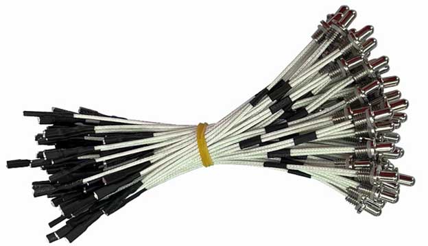
DALLAS デジタル温度センサー ワイヤーハーネス

DS18B20センサープローブ + ケーブル
 DS18B20デジタルセンサーコネクタハーネス
5.3. DS18B20センサーの外部電源モード
外部電源モードで, DS18B20センサー作業電源はVDDピンに接続されています. 現時点では, I/Oラインは強力なプルアップを必要としません, 電源が不十分な電流の問題はありません, これにより、変換の精度を確保できます. 同時に, 任意の数のDS18B20センサーを理論的にバスに接続して、マルチポイント温度測定システムを形成できます. 注記: 外部電源モードで, DS18B20のGNDピンを浮かんでいるままにすることはできません, それ以外の場合、温度を変換することはできず、読み取り温度は常に85°Cです.
外部電源法は、DS18b20センサーの最良の作業方法です. 作業は安定して信頼できます, 干渉防止能力は強いです, そして、回路は比較的単純です, したがって、安定した信頼性の高いマルチポイント温度監視システムを開発できます. ウェブマスターは、開発中に外部電源を使用することをお勧めします. 結局, 寄生電源よりもVCCリードが1つしかありません. 外部電源モードで, DS18B20の広い電源電圧範囲の利点は、完全に利用できます. 電源電圧VCCが3Vに低下しても, 温度測定精度は引き続き保証できます.
6. DS1820を使用する場合の注意事項
DS1820には単純な温度測定システムの利点がありますが, 高温測定精度, 便利な接続, より少ないインターフェイスラインを取り上げます, 以下の問題は、実際のアプリケーションでも注意を払う必要があります:
6.1. 小さなハードウェアオーバーヘッドには、補償するために比較的複雑なソフトウェアが必要です. シリアルデータ送信はDS1820とマイクロプロセッサの間で使用されるため, DS1820にプログラミングを読んで執筆するとき, 読み取りと書き込みのタイミングは厳密に保証する必要があります, それ以外の場合、温度測定の結果は読み取られません. システムプログラミングにPL/MやCなどの高レベル言語を使用する場合, アセンブリ言語を使用してDS1820操作パーツを実装するのが最善です.
6.2. DS1820の関連情報は、単一のバスに接続されたDS1820の数については言及していません, これは、DS1820の数を接続できると誤って人々を誤って信じることができるかもしれません. 実際のアプリケーションでは、そうではありません. それ以上があるとき 8 単一のバスでのDS1820, マイクロプロセッサのバスドライバーの問題を解決する必要があります. このポイントは、マルチポイント温度測定システムを設計する際に注意する必要があります.
6.3. DS1820に接続されたバスケーブルには長さの制限があります. テスト中, 通常の信号ケーブルを使用して、伝送長が50mを超える場合, 温度測定データの読み取りでエラーが発生します. バスケーブルがねじれたペアシールドケーブルに変更されたとき, 通常の通信距離は150mに達する可能性があります. 1メートルあたりのひねりを加えたツイストペアシールドケーブルを使用すると, 通常の通信距離はさらに延長されます. この状況は、主にバス分散容量によって引き起こされる信号波形の歪みによって引き起こされます. したがって, DS1820を使用して長距離温度測定システムを設計する場合, バス分散容量とインピーダンスマッチングの問題を完全に考慮する必要があります.
6.4. DS1820温度測定プログラムの設計, 温度変換コマンドをDS1820に送信した後, プログラムは常にDS1820からの返品信号を待ちます. DS1820の接触が不十分な場合、または切断されます, プログラムがDS1820を読み取るとき, リターン信号がなく、プログラムは無限ループを入力します. この点は、DS1820ハードウェア接続とソフトウェア設計を実行するときにも一定の注意を払う必要があります. 温度測定ケーブルを4コアツイストペアにシールドすることをお勧めします. 1つのワイヤーが接地ワイヤと信号ワイヤーに接続されています, 他のグループはVCCとグランドワイヤーに接続されています, そして、シールド層はソースエンドの単一のポイントに接地されています.
お問い合わせ
メールを待っています, 以内に返信させていただきます 12 必要な貴重な情報を何時間も入手できる.
 English
 Afrikaans
 العربية
 বাংলা
বাংলা bosanski jezik
 Български
 Català
 粤语
粤语 中文(简体)
 中文(漢字)
 Hrvatski
 Čeština
 Nederlands
 Eesti keel
 Suomi
Suomi Français
 Deutsch
 Ελληνικά
 हिन्दी; हिंदी
 Magyar
 Bahasa Indonesia
 Italiano
 日本語
日本語 한국어
한국어 Latviešu valoda
 Lietuvių kalba
 македонски јазик
 Bahasa Melayu
 Norsk
Norsk پارسی
پارسی Polski
 Português
 Română
 Русский
 Cрпски језик
 Slovenčina
 Slovenščina
 Español
 Svenska
 ภาษาไทย
 Türkçe
 Українська
 اردو
اردو Tiếng Việt

