製品カテゴリ
- サーマルサーキットブレーカー 20
- ヒューズボックスホルダー 36
- 温度センサー 67
- サーマルスイッチ 64
- カーヒューズ 19
- ボルトダウンヒューズ 7
- 温度ヒューズ 32
- 表面実装ヒューズ 12
- サーミスター 22
- PCB マウント ヒューズ ホルダー 27
- ワイヤハーネス 6
- ブレードヒューズホルダー 17
- サーモスタット 46
- 電気ヒューズ 14
製品タグ
Ds18b20 センサー プローブとケーブル
DS18B20 温度センサーの機能: 防水, 防食.
梱包詳細: 必要に応じてカスタマイズできます. MAXIMはオリジナルのパッケージで輸入されました; TO-92パッケージ; 大量に在庫あり. DS18B20 デジタル温度センサーをステンレス鋼管防水パッケージで提供します.
The ds18b20 temperature sensor probe has high accuracy. The temperature measurement accuracy can reach 0.01℃, and the temperature measurement accuracy in the wide temperature range is 0.1℃. Good stability and high precision in mass production.
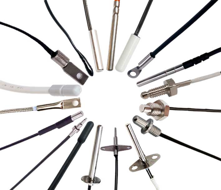
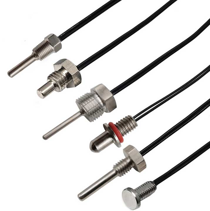
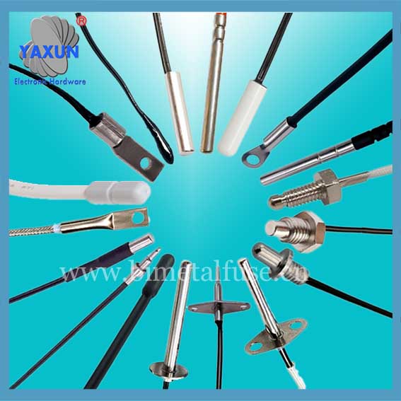
The DS18B20 digital sensor probe and cable are easy to connect and can be used in a variety of situations after being packaged. Such as stainless steel straight pipe type, ねじ込みタイプ, マグネット吸着タイプ, さまざまなモデル, LTM8877を含む, LTM8874など.
DS18B20 は一般的に使用されるデジタル温度センサーです. It outputs a digital signal and has the characteristics of small size, ハードウェアのオーバーヘッドが低い, strong anti-interference ability and high accuracy. Its appearance mainly changes depending on the application. The encapsulated DS18B20 can be used for cable temperature measurement, 爆発炉の循環温度測定, ボイラー温度測定, 機械の室温測定, 農業温室温度測定, クリーンな室温測定, ammunition depot temperature measurement and other non-limit temperature occasions. Wear-resistant and impact-resistant, small in size, 使いやすい, with various packaging forms, it is suitable for digital temperature measurement and control of various small space equipment.
Main features of DS18B20 sensor probe
1. Main features of DS18B20
1.1. The adaptable voltage range is wider, voltage range: 3.0~5.5V, and can be powered by the data line in parasitic power mode
1.2. Unique single-wire interface method. When DS18B20 is connected to the microprocessor, it only needs one port line to achieve two-way communication between the microprocessor and DS18B20.
1.3. DS18B20 supports multi-point networking function. Multiple DS18B20 can be connected in parallel on the only three lines to achieve multi-point temperature measurement.
1.4. DS18B20 does not require any external components during use. All sensing components and conversion circuits are integrated into an integrated circuit shaped like a triode.
1.5. Temperature range -55℃~+125℃, accuracy is ±0.5℃ at -10~+85℃
1.6. The programmable resolution is 9~12 bits, and the corresponding resolvable temperatures are 0.5℃, 0.25℃, 0.125℃ and 0.0625℃ respectively, which can achieve high-precision temperature measurement.
1.7. At 9-bit resolution, the temperature can be converted into numbers in up to 93.75ms. At 12-bit resolution, the temperature value can be converted into numbers in up to 750ms, which is faster.
1.8. The measurement results directly output digital temperature signals and are serially transmitted to the CPU via the "one-line bus". 同時に, the CRC check code can be transmitted, which has strong anti-interference and error correction capabilities.
1.9. Negative voltage characteristics: When the polarity of the power supply is reversed, the chip will not be burned due to heat, but it will not work properly.
2. Appearance and internal structure of DS18B20 sensor
The internal structure of the DS18B20 sensor mainly consists of four parts: 64-bit photolithography ROM, 温度センサー, 不揮発性温度アラームはTHとTLをトリガーします, and configuration register.
The appearance and pin arrangement of DS18B20 are as follows:
DS18B20 PIN定義:
(1) DQは、デジタル信号入力/出力端子です;
(2) GNDは電力場です;
(3) VDD is the input terminal of the external power supply (grounded in the parasitic power wiring mode).
3. Working principle of DS18B20
The reading and writing timing and temperature measurement principle of DS18B20 are the same as those of DS1820, except that the number of digits of the temperature value obtained is different due to different resolutions, and the delay time during temperature conversion is reduced from 2s to 750ms. The oscillation rate of high temperature coefficient crystal oscillator changes significantly with temperature changes, 生成された信号は、カウンターのパルス入力として使用されます 2. カウンタ 1 and the temperature register are preset at a base value corresponding to -55°C. カウンタ 1 counts down the pulse signal generated by the low temperature coefficient crystal oscillator. カウンターのプリセット値の場合 1 decreases to 0, 温度レジスタの値は 1, the preset value of counter 1 リロードされます, and counter 1 will restart counting the pulse signals generated by the low temperature coefficient crystal oscillator. This cycle continues until counter 2 カウント 0, then stops accumulating the temperature register value. 現時点では, 温度レジスタの値は測定温度です. The slope accumulator in Figure 3 is used to compensate and correct the nonlinearity in the temperature measurement process, およびその出力は、カウンターのプリセット値を修正するために使用されます 1.

ds18b20 sensor with accuracy up to 0.01℃

カスタマイズされた ds18b20 センサー プローブとケーブル
DS18b20にはあります 4 main data components:
(1) The 64-bit serial number in the photoetched ROM is photoetched before leaving the factory. It can be regarded as the address serial code of the DS18B20. The arrangement of the 64-bit photolithography ROM is: the first 8 ビット (28H) are the product type number, and the next 48 bits are the serial number of the DS18B20 itself. The last 8 bits are the cyclic redundancy check code of the previous 56 ビット (CRC=X8+X5+X4+1). The function of photolithography ROM is to make each DS18B20 different, 複数のDS18B20を1つのバスに接続できるように.
(2) The temperature sensor in DS18B20 can complete the measurement of temperature. Take 12-bit conversion as an example: it is provided in the form of 16-bit sign-extended two's complement reading, expressed in the form of 0.0625°C/LSB, ここで、Sはサインビットです.
This is the 12-bit data obtained after 12-bit conversion, which is stored in two 8-bit RAMs of 18B20. The first 5 bits in binary are the sign bits. If the measured temperature is greater than 0, these 5 bits are 0. Just multiply the measured value by 0.0625 to get the actual temperature. If the temperature is less than 0, these 5 bits are 1, and the measured value needs to be inverted, plus 1, and then multiplied by 0.0625 to get the actual temperature. 例えば, +125℃のデジタル出力は07d0hです, +25.0625のデジタル出力は0191Hです, the digital output of -25.0625℃ is FE6FH, -55℃のデジタル出力はFC90Hです.
(3) DS18B20 temperature sensor memory DS18B20. The internal memory of the temperature sensor includes a high-speed scratchpad RAM and a non-volatile electrically erasable EEPRAM, which stores the high-temperature and low-temperature flip-flops TH, TL and structural registers.
(4) Configuration register The meaning of each bit of this byte is as follows:
テーブル 3: Configuration register structure
The lower five bits are always "1", and TM is the test mode bit, which is used to set whether the DS18B20 is in working mode or test mode. This bit is set to 0 when DS18B20 leaves the factory, and users should not change it. R1 and R0 are used to set the resolution, as shown in the following table: (DS18B20 is set to 12 bits when shipped from the factory)
テーブル 4: Temperature resolution setting table
4. High-speed temporary storage memory The high-speed temporary storage memory consists of 9 バイト, and its allocation is shown in Table 5. When the temperature conversion command is issued, the converted temperature value is stored in the 0th and 1st bytes of the cache memory in two-byte complement form. The microcontroller can read this data through the single-wire interface. When reading, the low bit is in front and the high bit is in the back. The data format is shown in Table 1. Corresponding temperature calculation: When the sign bit S=0, directly convert the binary bit to decimal; when S=1, first convert the complement to the original code, and then calculate the decimal value. テーブル 2 shows some of the corresponding temperature values. The ninth byte is the redundancy check byte.
テーブル 5: DS18B20 temporary register distribution
According to the communication protocol of DS18B20, the host (single chip microcomputer) must go through three steps to control DS18B20 to complete temperature conversion: DS18B20 must be reset before each read and write. After the reset is successful, a ROM command is sent, and finally a RAM command is sent, so that the predetermined operation can be performed on the DS18B20. Reset requires the main CPU to pull the data line down for 500 microseconds and then release it. When DS18B20 receives the signal, it waits for about 16 に 60 マイクロ秒, and then sends out a low pulse of 60 に 240 マイクロ秒. The main CPU receives this signal to indicate successful reset.
テーブル 6: ROM instruction list
お問い合わせ
メールを待っています, 以内に返信させていただきます 12 必要な貴重な情報を何時間も入手できる.
 English
 العربية
 Български
 粤语
粤语 中文(简体)
 中文(漢字)
 Nederlands
 Suomi
Suomi Français
 Deutsch
 Ελληνικά
 Magyar
 Italiano
 日本語
日本語 한국어
한국어 Polski
 Português
 Română
 Русский
 Slovenščina
 Español
 Svenska
 ภาษาไทย
 Türkçe
 Tiếng Việt

