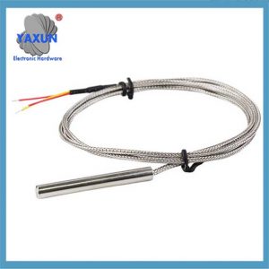
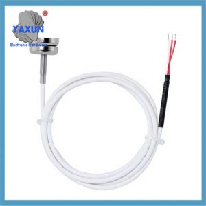
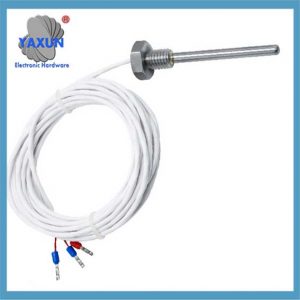
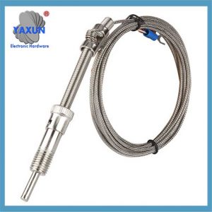
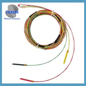
PT100 または PT1000 センサー プローブの温度取得回路は通常、センサーを励起する安定した電流源で構成されます。, 温度による抵抗値の変化を検出する高精度抵抗測定回路, そしてアナログデジタルコンバーター (ADC) 測定された電圧を、マイクロコントローラーまたはデータ収集システムで処理できるデジタル信号に変換します。; PT100 回路と PT1000 回路の主な違いは、Pt100 の公称抵抗値が 100 であるため、抵抗値のスケールです。 100 Pt1000 は 0°C でのオームを持ちます。 1000 0℃でのオーム, 多くの場合、必要な精度や用途に応じて測定回路の調整が必要になります.
この記事では、さまざまな温度における PT100 および PT1000 金属熱抵抗センサー プローブの抵抗変化を紹介します。, さまざまな温度取得回路ソリューションも. 抵抗分圧含む, 橋梁測定, 定電流源とAD623, AD620 収集回路. 干渉を防ぐために, 特に航空宇宙分野における電磁干渉, 空中 PT1000 温度センサー取得回路設計が提案されています, フィルタリングと測定精度の向上のための T 型フィルターを含む.
インテリジェントなテクノロジーを通じて CSDN によって生成された要約
PT100/PT1000温度取得回路ソリューション
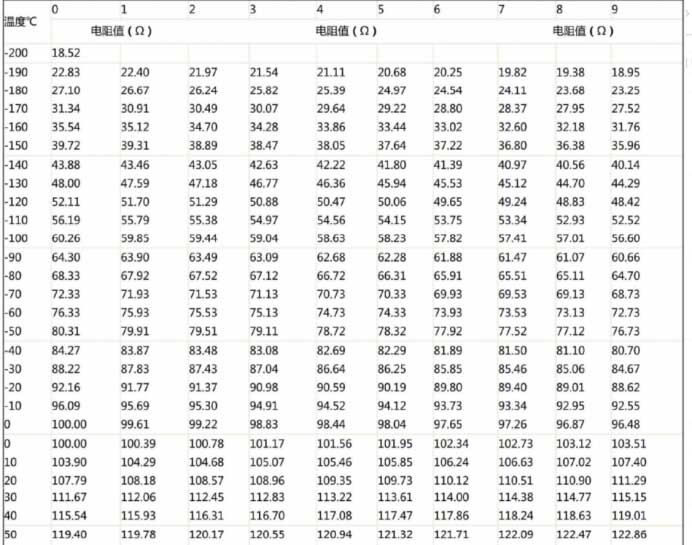
1. PT100およびPT1000センサーの温度抵抗変化表
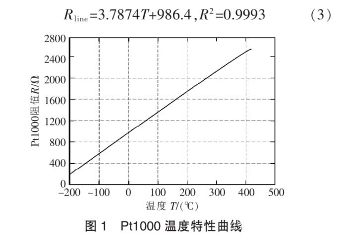
ニッケルなどの金属熱抵抗器, 銅抵抗と白金抵抗は温度変化と正の相関関係があります。. プラチナは物理的および化学的特性が最も安定しており、最も広く使用されています。. 一般的に使用される白金抵抗Pt100センサープローブの温度測定範囲は-200~850℃です。, Pt500の温度測定範囲と, Pt1000センサープローブ, 等. 次々と減額されていく. Pt1000, 温度測定範囲は-200~420℃. 国際規格IEC751に準拠, 白金抵抗器 Pt1000 の温度特性は以下の要件を満たします。:
Pt1000の温度特性曲線による, 抵抗特性曲線の傾きは、通常の動作温度範囲内でわずかに変化します。 (図に示すように 1). 抵抗と温度のおおよその関係は、線形フィッティングによって取得できます。:
2. 一般的に使用される収集回路ソリューション
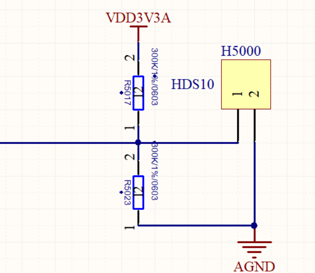
2. 1 抵抗分圧器出力 0~3.3V/3Vアナログ電圧シングルチップADポート直接取得
温度測定回路の電圧出力範囲は0~3.3Vです。, PT1000 (PT1000は抵抗値が大きく変化します, 温度測定感度は PT100 よりも高い; PT100は大規模な温度測定に適しています).
最も簡単な方法は分圧方式を使用することです。. 電圧はTL431電圧基準源チップによって生成されます。, これは4Vの基準電圧源です. あるいは, REF3140 を使用して、基準電源として 4.096V を生成できます。. リファレンスソースチップにはREF3120も含まれます, 3125, 3130, 3133, そして 3140. チップはSOT-32パッケージと5Vの入力電圧を使用します. 必要な基準電圧に応じて出力電圧を選択可能. もちろん, マイクロコントローラーのADポートの通常の電圧入力範囲に応じて, 3V/3.3Vを超えることはできません.
2.2 抵抗分圧出力 0~5Vアナログ電圧, そしてマイクロコントローラーのADポートがそれを直接収集します.
もちろん, 一部の回路は 5V マイクロコントローラーから電力を供給されています, PT1000の最大動作電流は0.5mAです。, したがって、コンポーネントの正常な動作を保証するには、適切な抵抗値を使用する必要があります。.
例えば, 上の分圧回路図の 3.3V は 5V に置き換えられます。. この利点は、5V の分圧が 3.3V の電圧よりも敏感であることです。, そしてコレクションはより正確になります. 覚えて, 理論的に計算された出力電圧は +5V を超えることはできません. さもないと, マイクロコントローラーが壊れる.
2.3 最も一般的に使用される橋梁測定
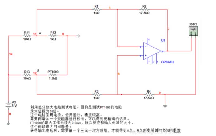
R11を使用する, R12, R13 と Pt1000 で測定ブリッジを形成, ここで、R11=R13=10k, R12=1000R 精密抵抗器. Pt1000の抵抗値とR12の抵抗値が異なる場合, ブリッジはmVレベルの電圧差信号を出力します。. この電圧差信号が計器用増幅回路で増幅され、所望の電圧信号が出力されます。, AD変換チップやマイコンのADポートに直接接続可能.
この回路の抵抗測定原理:
1) PT1000はサーミスタです, その抵抗は温度の変化に対して基本的に直線的に変化します.
2) で 0 度, PT1000の抵抗は1kΩです, Ub と Ua は等しい, あれは, ウバ=ウブ – する = 0.
3) ある温度だと仮定すると、, PT1000の抵抗は1.5kΩです, Ub と Ua は等しくありません. 分圧器の原理によると, ウバ = Ub を見つけることができます – する > 0.
4) OP07はオペアンプです, 電圧増幅率Aは外部回路に依存します, ここで、A = R2/R1 = 17.5.
5) OP07の出力電圧Uo = Uba * あ. したがって、電圧計を使用してOP07の出力電圧を測定すると、, Uab の価値を推測できます. Ua は既知の値なので、, Ub の値をさらに計算できます. それから, 分圧器の原理を使用する, PT1000の比抵抗値を計算できます. このプロセスはソフトウェア計算によって実現できます。.
6) PT1000の任意の温度における抵抗値がわかれば, 現在の温度を知るには、抵抗値に従ってテーブルを参照するだけで済みます。.
2.4 定電流源
感熱抵抗体の自己発熱効果により, 抵抗器を流れる電流をできるだけ小さくする必要があります。, 一般に、電流は 10mA 未満であると予想されます。. の白金抵抗器PT100の自己発熱が確認されております。 1 mW は次の温度変化を引き起こします。 0.02 ~0.75℃, したがって、白金抵抗器 PT100 の電流を減らすと、その温度変化も減らすことができます。. しかし, 電流が小さすぎる場合, ノイズ干渉を受けやすい, したがって、一般的には次のように取られます 0.5 に 2 ミリアンペア, したがって、定電流源の電流は 1mA の定電流源として選択されます。.
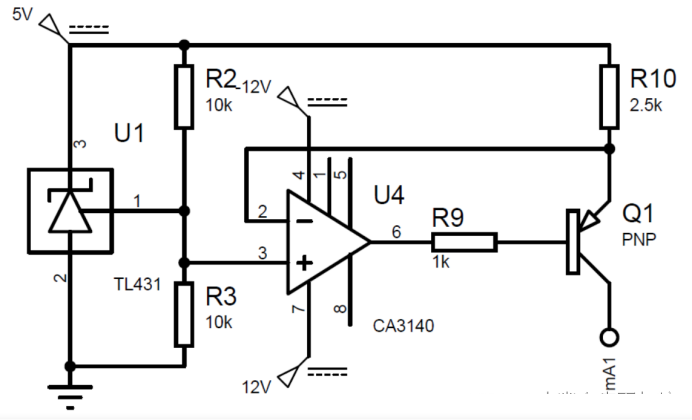
選択したチップは定電圧源チップ TL431 です, そして、電流の負帰還を使用して定電流源に変換します。. 回路は図に示されています:
オペアンプCA3140は電流源の負荷容量を向上させるために使用されます。, 出力電流の計算式は次のようになります。:
ここに画像の説明を挿入します。抵抗器は 0.1% 精密抵抗器. 最終出力電流は0.996mAです。, あれは, 精度は 0.4%.
定電流源回路は次のような特性を持つ必要があります。:
温度安定性: 弊社の温度測定環境は0~100℃ですので, 電流源の出力は温度に敏感であってはなりません. TL431 は非常に低い温度係数と低い温度ドリフトを備えています。.
優れた負荷レギュレーション: 電流リップルが大きすぎる場合, 読み取りエラーの原因になります. 理論分析によると. 入力電圧は100~138.5mVの間で変動するため、, 温度測定範囲は0〜100℃です。, 温度測定精度は±1℃です。, したがって、周囲温度が1℃上昇するごとに、出力電圧は38.5/100=0.385mV変化するはずです。. 電流変動が精度に影響を与えないようにするため, 最も極端なケースを考えてみる, で 100 摂氏, PT100の抵抗値は138.5Rである必要があります。. この場合、電流リップルは 0.385/138.5=0.000278mA 未満になるはずです。, あれは, 負荷変化時の電流変化は0.000278mA未満である必要があります。. 実際のシミュレーションでは, 電流源は基本的に変更されません.
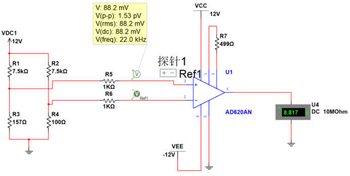
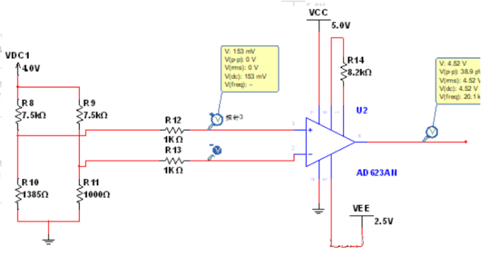
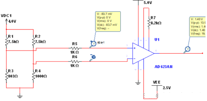
3. AD623 集録回路ソリューション
この原理は、上記の橋梁測定原理を参照できます。.
低温取得:
高温取得
ここに画像の説明を挿入します
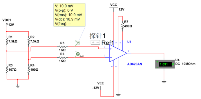
4. AD620 集録回路ソリューション
AD620 PT100 高温用取得ソリューション (150°):
AD620 PT100 低温用取得ソリューション (-40°):
AD620 PT100 室温用取得ソリューション (20°):
5. PT100 および PT1000 センサーの干渉防止フィルター分析
いくつかの複合施設での温度取得, 過酷な環境や特殊な環境では大きな干渉を受ける可能性があります, 主にEMIとREIを含む. 例えば, モーター温度取得用途で, モーター制御やモーターの高速回転に伴う高周波外乱.
航空および航空宇宙車両の内部には、多数の温度制御シナリオもあります。, 電力システムや環境制御システムの計測・制御を行う. 温度管理の核心は温度測定. サーミスタの抵抗は温度に応じて直線的に変化するため、, 白金抵抗を使用した温度測定は効果的な高精度温度測定方法です. 主な問題点は以下の通り:
1. リード線に抵抗が入りやすい, したがって、センサーの測定精度に影響します。;
2. 特定の強い電磁干渉環境では, 干渉は、計測器アンプによって整流された後、DC 出力オフセット誤差に変換される可能性があります。, 測定精度に影響を与える.
5.1 航空宇宙航空機搭載 PT1000 取得回路
特定の航空における電磁干渉防止のための空中 PT1000 収集回路の設計を参照してください。.
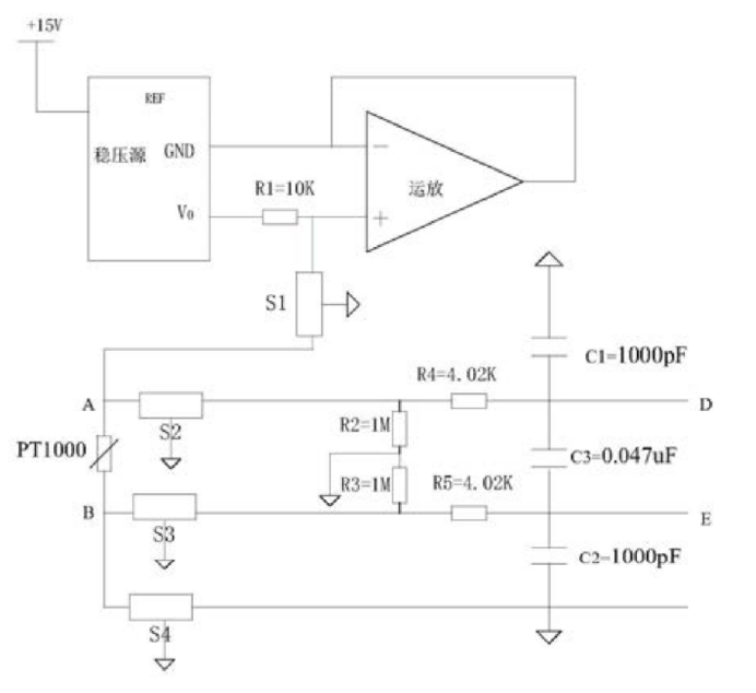
取得回路の最外端にフィルタを設置. PT1000 取得前処理回路は、航空機搭載電子機器インターフェイスの電磁干渉防止前処理に適しています。; 具体的な回路は:
+15V 入力電圧は、電圧レギュレータを介して +5V 高精度電圧源に変換されます。. +5V 高精度電圧源は抵抗 R1 に直接接続されています。, 抵抗R1の他端は2つの経路に分かれています. 1 つはオペアンプの同相入力端に接続されています, もう1つはT型フィルタS1を介してPT1000の抵抗A端に接続されています. オペアンプの出力は反転入力に接続され、ボルテージフォロワを形成します。, そして反転入力は電圧レギュレータのグランドポートに接続され、同相入力の電圧が常にゼロになるようにします。. S2フィルター通過後, PT1000 抵抗の一端 A は 2 つの経路に分かれています, 1 つは差動電圧入力として抵抗 R4 を介して D, 1 つは抵抗 R2 を介して AGND に接続. S3フィルター通過後, PT1000 抵抗の他端 B は 2 つの経路に分かれています, 1 つは差動電圧入力 E として抵抗 R5 を介して, 1 つは抵抗 R3 を介して AGND に接続. DとEはコンデンサC3を介して接続されています, DはコンデンサC1を介してAGNDに接続されています, EはコンデンサC2を介してAGNDに接続されています. PT1000 の正確な抵抗値は、D と E 間の差動電圧を測定することで計算できます。.
+15V 入力電圧は、電圧レギュレータを介して +5V 高精度電圧源に変換されます。. +5VはR1に直接接続されています. R1 の他端は 2 つのパスに分かれています, 1 つはオペアンプの同相入力に接続されています, もう1つはT型フィルタS1を介してPT1000抵抗のA端に接続されています. オペアンプの出力は反転入力に接続され、ボルテージフォロワを形成します。, 反転入力は電圧レギュレータのグランドポートに接続され、反転入力の電圧が常にゼロになるようにします。. 現時点では, R1を流れる電流は一定の0.5mAです。. 電圧レギュレータにはAD586TQ/883Bを使用, オペアンプにはOP467Aを使用.
S2フィルター通過後, PT1000 抵抗の一端 A は 2 つの経路に分かれています, 1 つは差動電圧入力端として抵抗 R4 を介して D, 1 つは抵抗 R2 を介して AGND に接続. S3フィルター通過後, PT1000 抵抗の他端 B は 2 つの経路に分かれています, 1つは抵抗R5を介して差動電圧入力端Eとして, 1 つは抵抗 R3 を介して AGND に接続. DとEはコンデンサC3を介して接続されています, DはコンデンサC1を介してAGNDに接続されています, EはコンデンサC2を介してAGNDに接続されています.
R4とR5の抵抗は4.02kオームです。, R1とR2の抵抗は1Mオームです, C1とC2の静電容量は1000pFです, C3の静電容量は0.047uFです。. R4, R5, C1, C2, と C3 は一緒になって RFI フィルター ネットワークを形成します. RFI フィルターは入力信号のローパス フィルター処理を完了します。, フィルタリングされるオブジェクトには、入力差動信号に含まれる差動モード干渉とコモンモード干渉が含まれます。. 入力信号に含まれるコモンモード干渉とディファレンシャルモード干渉の -3dB カットオフ周波数の計算は次の式で示されます。:
抵抗値を計算に代入する, コモンモードカットオフ周波数は40kHzです, 差動モードのカットオフ周波数は2.6KHZです。.
エンドポイント B は S4 フィルターを介して AGND に接続されます. その中で, S1 から S4 までのフィルター接地端子はすべて航空機のシールド接地に接続されています。. PT1000に流れる電流は既知の0.05mAであるため、, PT1000 の正確な抵抗値は、D と E の両端の差動電圧を測定することで計算できます。.
S1~S4はT型フィルターを使用, 型式 GTL2012X‑103T801, カットオフ周波数M±20%. この回路は、外部インターフェイス ラインにローパス フィルターを導入し、差動電圧に対して RFI フィルター処理を実行します。. PT1000の前処理回路として, 電磁波およびRFI放射干渉を効果的に排除します。, これにより、収集された値の信頼性が大幅に向上します。. 加えて, 電圧は PT1000 抵抗器の両端から直接測定されます。, リード線抵抗による誤差をなくし、抵抗値の精度を向上させます。.
5.2 T型フィルター
ここに画像の説明を挿入します
T型フィルタは2つのインダクタとコンデンサで構成されます. 両端がハイインピーダンスになっている, 挿入損失性能はπ型フィルタと同等です。, しかし、その傾向はありません “鳴っている” スイッチング回路で使用可能.
 English
 Afrikaans
 العربية
 বাংলা
বাংলা bosanski jezik
 Български
 Català
 粤语
粤语 中文(简体)
 中文(漢字)
 Hrvatski
 Čeština
 Nederlands
 Eesti keel
 Suomi
Suomi Français
 Deutsch
 Ελληνικά
 हिन्दी; हिंदी
 Magyar
 Bahasa Indonesia
 Italiano
 日本語
日本語 한국어
한국어 Latviešu valoda
 Lietuvių kalba
 македонски јазик
 Bahasa Melayu
 Norsk
Norsk پارسی
پارسی Polski
 Português
 Română
 Русский
 Cрпски језик
 Slovenčina
 Slovenščina
 Español
 Svenska
 ภาษาไทย
 Türkçe
 Українська
 اردو
اردو Tiếng Việt

