 English
 Afrikaans
 العربية
 বাংলা
বাংলা bosanski jezik
 Български
 Català
 粤语
粤语 中文(简体)
 中文(漢字)
 Hrvatski
 Čeština
 Nederlands
 Eesti keel
 Suomi
Suomi Français
 Deutsch
 Ελληνικά
 हिन्दी; हिंदी
 Magyar
 Bahasa Indonesia
 Italiano
 日本語
日本語 한국어
한국어 Latviešu valoda
 Lietuvių kalba
 македонски јазик
 Bahasa Melayu
 Norsk
Norsk پارسی
پارسی Polski
 Português
 Română
 Русский
 Cрпски језик
 Slovenčina
 Slovenščina
 Español
 Svenska
 ภาษาไทย
 Türkçe
 Українська
 اردو
اردو Tiếng Việt
2-draad, 3-wire or 4-wire Pt100, Pt500, Pt1000 sensors are temperature sensors based on platinum elements with high accuracy, stability and linearity, and are widely used in fields that require accurate temperature measurement. A “PT100 thermal resistor temperature measurement system” refers to a system that uses a PT100 sensor, a type of Resistance Temperature Detector (OTO), to measure temperature by detecting changes in its electrical resistance which are directly proportional to the temperature; “PT” stands for Platinum, En “100” indicates that the sensor has a resistance of 100 ohms at 0°C making it a highly accurate and stable method for temperature measurement across a wide range.
Platinaweerstanden worden veel gebruikt in het middentemperatuurbereik (-200~650℃). Momenteel, Er zijn standaard temperatuurmeetweerstanden van metaalplatina op de markt, zoals Pt100, Pt500, Pt1000, enz.
Understand the working principle of PT100: PT100 is a temperature sensor of Pt resistor. The working principle is based on the thermal effect of resistor. Its resistance value changes with the change of temperature. This change is linear. At 0℃, the resistance value of PT100 is 100 ohm. As the temperature rises, the resistance value also increases accordingly, so the temperature can be accurately inferred by measuring the resistance value.
 Uiterst nauwkeurig 4-draads klasse A PT100-temperatuurmeetsysteem |
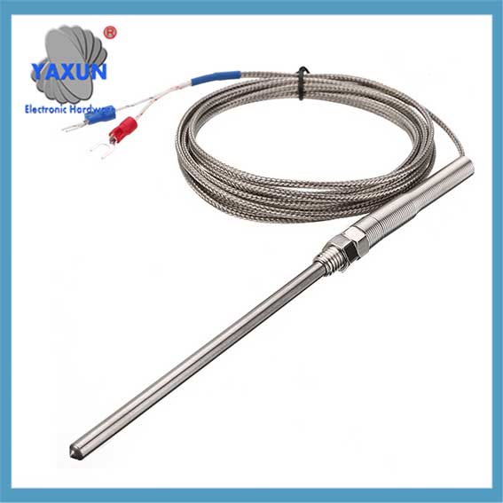 2-wire PT100 platinum resistance temperature control probe temperature measurement system |
 3-wire PT100 thermal resistor sensor temperature measurement system |
Choose the appropriate wiring method: Algemeen, 2-draad, 3-wire or 4-wire wiring methods can be used.
The voltage signal output by the bridge
Key points about a PT100 system:
Sensor principle:
The PT100 sensor is made of a platinum wire whose electrical resistance changes predictably with temperature fluctuations.
Measurement method:
When a current is passed through the PT100, De spanningsval over de sensor wordt gemeten, die vervolgens wordt omgezet in temperatuur op basis van de bekende relatie tussen weerstand en temperatuur.
Brede toepassing:
PT100 -sensoren worden vaak gebruikt in industriële processen, laboratoria, en andere toepassingen waar precieze temperatuurmeting vereist is vanwege hun hoge nauwkeurigheid en stabiliteit.
Componenten van een PT100 -systeem:
PT100 -sensorsonde:
Het eigenlijke detectie -element, Meestal een platinadraad gewikkeld rond een keramische kern, die in de te gemeten omgeving wordt ingevoegd.
Signaalconditioneringscircuit:
Elektronica die de kleine weerstandsverandering van de PT100 versterken en omzetten in een meetbaar spanningssignaal.
Display- of data -acquisitiesysteem:
Apparaat dat de gemeten temperatuur weergeeft of de gegevens opslaat voor analyse.
Voordelen van het gebruik van een PT100 -systeem:
Hoge nauwkeurigheid: Beschouwd als een van de meest nauwkeurige temperatuursensoren die beschikbaar zijn.
Groot temperatuurbereik: Kan temperaturen meten van -200°C tot 850°C, afhankelijk van het sensorontwerp.
Goede lineariteit: De relatie tussen weerstand en temperatuur is erg lineair, Zorgen voor eenvoudige gegevensinterpretatie.
Stabiliteit: Platina is een zeer stabiel materiaal, Zorgen voor consistente metingen in de loop van de tijd.
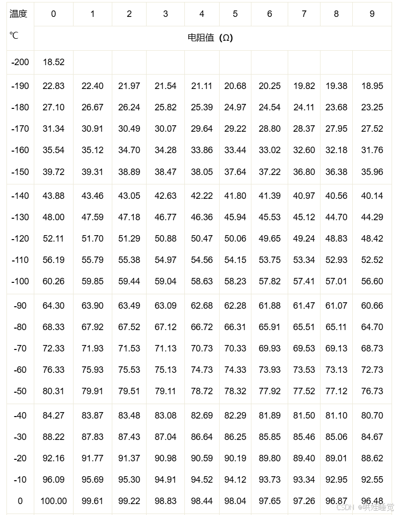
PT100 thermische weerstand indexeringstabel
De drie bedradingsmethoden van PT100 platinaristor zijn in principe verschillend: 2-Draad en 3-draads worden gemeten met een brugmethode, en de relatie tussen temperatuurwaarde en analoge uitgangswaarde wordt in het einde gegeven. 4-Draad heeft geen brug. Het wordt volledig verzonden door constante stroombron, gemeten door voltmeter, en geeft ten slotte de gemeten weerstandswaarde, wat moeilijk en kostbaar is om te gebruiken.
Omdat PT100 een kleine weerstandswaarde en hoge gevoeligheid heeft, De weerstandswaarde van de looddraad kan niet worden genegeerd. The use of 3-wire connection can eliminate the measurement error caused by the lead line resistance.
The 2-wire system has poor measurement accuracy; the 3-wire system has better accuracy; the 4-wire system has high measurement accuracy, but requires more wires.
We only need to know the temperature state of PT100 based on the voltage signal output by the bridge. When the resistance value of PT100 is not equal to the resistance value of Rx, the bridge outputs a differential pressure signal, which is very small. Since the output signal of the temperature sensor is generally very weak, a signal conditioning and conversion circuit is required to amplify it or convert it into a form that is easy to transmit, process, record and display. The slight change in the measured signal quantity needs to be converted into an electrical signal. When amplifying the DC signal, the self-drift and unbalanced voltage of the op amp cannot be ignored when passing through the op amp. After amplification, a voltage signal of the desired size can be output.
The resistance value of the platinum resistor can be obtained by circuit calculation or multimeter measurement. When we know the resistance value of PT100, we can measure and calculate the temperature by the resistance value.
Use appropriate algorithms for data processing: Use the known temperature and resistance relationship to calculate the temperature through programming. Considering that the resistance-temperature relationship of PT100 is nonlinear, especially in low or high temperature areas, more complex algorithms may be needed to improve accuracy.
Impact of environmental factors: Performance may be affected by environmental factors such as electromagnetic interference, mechanical vibration, and humidity.
There are three common temperature measurement calculation methods:
Temperature measurement calculation method 1:
When the exact temperature is not needed, the temperature will increase by 2.5℃ for every ohm increase in the resistance value of the PT100 thermal resistor (used at low temperatures). The resistance value of the PT100 temperature sensor is 100 when it is 0℃, so the approximate temperature at this time = (PT100 resistance value-100)*2.5.
Temperature measurement calculation method 2:
Relationship between the resistance value and temperature of platinum resistor
In the range of 0~850℃: Rt=R0(1+AT+BT2);
In the range of -200~0℃: Rt=R0[1+At+Bt2+C(t-100)3];
Rt represents the resistance value of platinum resistor at temperature t℃;
R0 represents the resistance value of platinum resistor at temperature 0℃;
A, B, C are constants, A=3.96847×10⁻³/℃; B=-5.847×10⁻⁷/℃; C=-4.22×10⁻¹²/℃;
For the thermal resistor that meets the above relationship, its temperature coefficient is about 3.9×10⁻³/℃.
Through the above formula, the temperature can be accurately solved according to the resistance value, but due to the large amount of calculation of this method, it is not recommended for this experiment.
Temperature calculation method three:
PT100 has a good linear relationship with temperature and is suitable for medium and low temperature temperature measurement. De weerstandswaarde van PT100 bij verschillende temperaturen heeft een één-op-één overeenkomstige meetschaal zoals weergegeven in de onderstaande figuur, die intuïtief de overeenkomstige relatie tussen verschillende temperaturen en de weerstandswaarde van PT100 kunnen weergeven.
De temperatuur kan bekend zijn door de overeenkomstige weerstandswaarde te controleren via de PT100 -schaal.
PT100 thermische weerstandsschaal
Het PT100-temperatuurmeetapparaat dat in dit artikel is ontworpen, maakt gebruik.
1.1 Spanningsbroncircuit
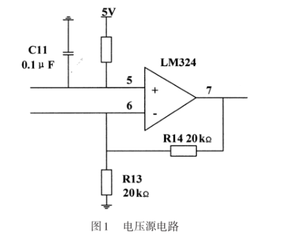
PT100 thermische weerstandssensorspanningsbroncircuit
Het circuit in figuur 1 is een gemeenschappelijk proportioneel operationeel circuit. Volgens de analyse van de ideale operationele versterker die in de lineaire regio werkt, Volgens het principe van virtuele korte en virtuele pauze, het wordt verkregen:
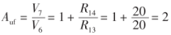
Wheatstone Bridge -berekening Circuit Formule
, dan is de gesloten-lusspanningsversterkingsfactor 2 keer, en dan wordt v = 10V verkregen, en het wordt gebruikt als de stabiele voedingsspanning van het Wheatstone -brugcircuit.
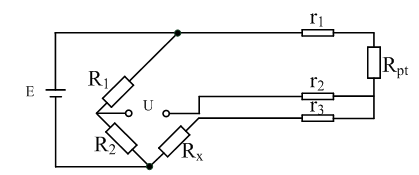
1.2 Drie-draads verbinding van Wheatstone Bridge en PT100.
Het bovenstaande figuur is een Wheatstone -brug. De voorwaarde dat de brug in evenwicht kan worden gebalanceerd, is dat de potentialen van punten B en D gelijk zijn. Dus als de brug in balans is, Zolang R1, R2 (meestal vaste waarden) en R0 (Meestal verstelbare waarden) worden gelezen, De te gemeten weerstand RX kan worden verkregen. R1/r2 = m, genaamd “vermenigvuldiger”.
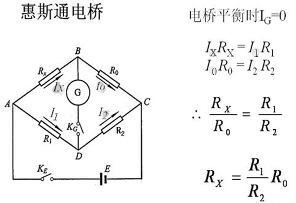
Wheatstone Bridge en PT100 drie-draads verbindingsmethode
According to the PT100 temperature measurement principle, the resistance value of PT100 needs to be known correctly, but the resistance value cannot be measured directly, so a conversion circuit is required. The resistance value is converted into a voltage signal that can be detected by the microcontroller”. The Wheatstone bridge circuit is an instrument that can correctly measure resistance. Zoals getoond in figuur 2, R1, R2, R3, and R4 are its bridge arms respectively. When the bridge is balanced, R1xR3=R2xR4 is satisfied. When the bridge is unbalanced, there will be a voltage difference between points a and b. According to the voltage of points a and b, the corresponding resistance can be calculated. This is the principle of measuring resistance with an unbalanced bridge:
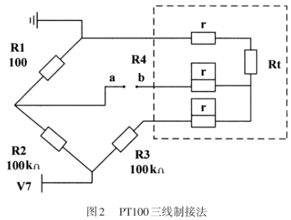
PT100 three-wire circuit connection method
In werkelijkheid, Vanwege de kleine weerstand en hoge gevoeligheid van PT100, De weerstand van de looddraad zal fouten veroorzaken. Daarom, De drie-draads verbindingsmethode wordt vaak gebruikt in de industrie om deze fout te elimineren. Zoals getoond in het gestippelde deel van de figuur 2, De weerstandswaarde van de looddraad is gelijk en is r. Op dit moment, De brugarmen worden r, R, R+2R, en RT+2R. When the bridge is balanced: R2. (R1+2R) = R1.(R3+2R), uitgelost: RT = R1R3/ R2+2 R1R/ R2- 2R. Analyse toont aan dat wanneer R1 = R2, De verandering in draadweerstand heeft geen effect op het meetresultaat.
1.3 Drie-op-amp instrumenten versterkercircuit
Wanneer de temperatuur verandert van 0 ℃ ~ 100 ℃, De weerstand van PT100 verandert ongeveer lineair in het bereik van 100Ω ~ 138,51Ω. Volgens het bovenstaande brugcircuit, De brug is gebalanceerd op 0 ℃, Dus de theoretische waarde van de uitgangsspanning van de brug moet zijn 0 V, en wanneer de temperatuur 100 ℃ is, De bruguitgang is: Uab = u7x(R1/(R1+ R2)-R3/(R2 + R3)), dat is, UAB = 10x(138.51/(10000 + 138.51)-100/(10000 + 100)) = 0,037599v. Omdat dit een Millivolt -signaal is, Het is noodzakelijk om deze spanning te versterken om deze door de AD -chip te detecteren.
Zoals getoond in figuur 3, De instrumentatieversterker is een apparaat dat kleine signalen versterkt in een lawaaierige omgeving. Het heeft een reeks voordelen zoals lage drift, Laag stroomverbruik, Hoge afwijzingsverhouding, breed voedingsbereik en klein formaat. Het gebruikt de kenmerken van differentiële kleine signalen gesuperponeerd op grotere gemeenschappelijke signalen, die gemeenschappelijke modussignalen kunnen verwijderen en differentiaalsignalen tegelijkertijd kunnen versterken. De uitgangsspanning van het standaard drie-op-amp instrumentatie-versterkercircuit is, Hier r8 = r10 = 20 kΩ, R9=R11=20 kΩ, R4=R7=100kΩ, which can amplify the input voltage signal by about 150 keer, so that the theoretical output voltage of the bridge can be amplified to 0 ~2.34 V. But this is only a theoretical value. In the actual process, there are many factors that can cause resistance changes. Daarom, R3 can be replaced with a precision adjustable resistor to facilitate circuit zeroing.
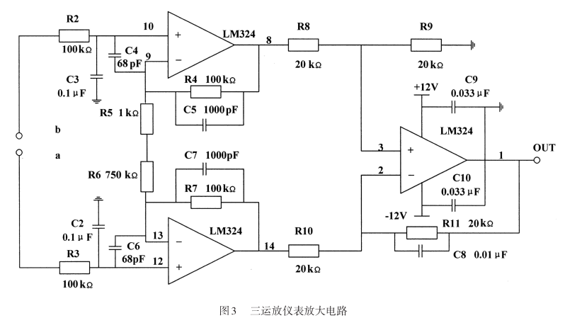
PT100 sensor three-op amp instrument amplifier circuit
2. Software Design
2.1 Least Squares Method and PT100 Linear Fitting
In the temperature range of 0℃≤t≤850℃, the relationship between Pt100 resistance and temperature is: R=100 (1 +AT+BT2), where A=3.90802x 10⁻³; B=- -5.80X 10⁻⁷; C=4.2735 x 10⁻¹²
It can be seen that the resistance of PT100 and temperature are not an absolute linear relationship but a parabola. Daarom, if t is to be extracted, a square root operation is required, which introduces a more complex function operation and occupies a large amount of CPU resources of the single-chip microcomputer. To solve this problem, we can use the least squares method to linearly fit the relationship between temperature and resistance. ” The least squares curve fitting is a common method for experimental data processing. Its principle is to find a polynomial function to minimize the sum of square errors with the original data.
2.2 AD digital conversion temperature
The PT100 temperature measurement principle is to obtain the temperature value based on its resistance value, so the resistance value of the thermal resistor must be determined first. According to the hardware circuit, the relationship between the output voltage Uab of the bridge circuit and the output voltage Uad of the op amp instrument amplifier circuit is: Uad=Uab. Auf Because the system uses a 12-bit AD chip, the relationship between the digital quantity and the analog quantity is: Uad/AD=5/4096. The relationship between the bridge output voltage and the digital quantity AD can be obtained by combining the previous two equations, dat is, Uad/AD=5/(4096Auf). Dan, it is substituted into the bridge output voltage expression Uab= U7x (Rt/ (R1+Rt) -R3/ (R2+R3) ), and the expression of Rr and the digital quantity AD can be obtained. The solution is:
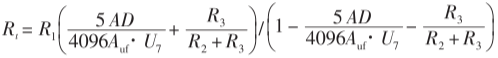
AD digital conversion temperature formula
After knowing the resistance value of PT100, the corresponding temperature value can be obtained according to the linear fitting equation in Section 2.1.
2.3 Single-chip digital filtering
In order to improve the temperature measurement accuracy of PT100, a digital filtering program can be added in the software programming, which does not require the addition of hardware circuits and can improve the stability and reliability of the system. There are many filtering methods in the single-chip microcomputer application system. When making a specific selection, the advantages and disadvantages of the filtering method and the applicable objects should be analyzed and compared, so as to select the appropriate filtering method. The algorithm of the median average filtering method is to first continuously collect N data, then remove a minimum value and a maximum value, and finally calculate the arithmetic mean of the remaining data. This filtering method is suitable for measuring parameters that change slowly, such as temperature, and can effectively reduce the interference caused by fluctuations caused by accidental factors or errors caused by sampler instability.
System working process:
When the temperature of the object being measured changes, the resistance of PT100 changes, and the Wheatstone bridge will output a corresponding voltage signal. This signal is a function of the resistance of PT100. This millivolt signal is amplified by a three-op-amp instrumentation amplifier and sent to the AD chip, which converts the analog quantity into a digital quantity and is read by the microcontroller. The microcontroller reads the chip from the AD chip and executes the filtering program, De stabiele digitale hoeveelheid omzetten in de weerstand van PT100 door berekening. Vervolgens selecteert de microcontroller het overeenkomstige gepaste lineaire model volgens de grootte van de weerstandswaarde om de huidige temperatuurwaarde te berekenen, en geef uiteindelijk de temperatuurgegevens weer op het LCD -display.