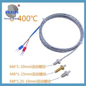
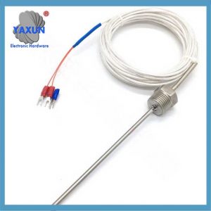
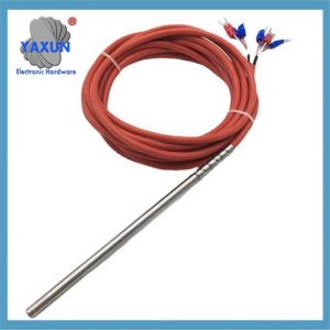
The article introduces how 2, 3, and 4-wire PT100 sensors are converted into voltage signals through resistance changes, and a constant current source is used to protect the sensor and ensure the accuracy of signal conversion. Um sensor PT100 adquire temperatura medindo a mudança em sua resistência elétrica, que se correlaciona diretamente com a temperatura a que está exposto; à medida que a temperatura aumenta, a resistência do elemento de platina dentro do sensor também aumenta, permitindo um cálculo preciso da temperatura com base nesta mudança de resistência; essencialmente, o “100” em PT100 significa que o sensor tem uma resistência de 100 ohms a 0°C, e este valor muda previsivelmente com as flutuações de temperatura. The application of the MCP604 operational amplifier in circuit design emphasizes the impact of its characteristics such as low input offset voltage and bias current on accuracy. Software calibration is used to improve accuracy in circuit design, avoiding the inconvenience of physical adjustment. Finally, the article gives the relationship formula between temperature and platinum resistance value, which is used to calculate the temperature value.
Key points about PT100 temperature acquisition:
Detector de temperatura de resistência (IDT):
PT100 is a type of RTD, meaning it measures temperature by detecting changes in its electrical resistance.
Platinum element:
The sensing element in a PT100 is made of platinum, which exhibits a very stable and linear relationship between resistance and temperature.
Measurement process: The sensor is placed in the environment where the temperature needs to be measured.
The resistance of the platinum element is measured using a dedicated electronic circuit.
The measured resistance value is then converted to temperature using a mathematical formula based on the known temperature coefficient of platinum.
Advantages of PT100 sensors:
Alta precisão: Considered one of the most accurate temperature sensors available due to the stable behavior of platinum.
Wide temperature range: Can measure temperatures from -200°C to 850°C depending on the sensor design.
Boa linearidade: The relationship between resistance and temperature is relatively linear, simplifying data interpretation.
Important considerations:
Calibration: To ensure accurate measurements, PT100 sensors need to be regularly calibrated against a reference standard.
Lead wire resistance: The resistance of the connecting wires can affect the measurement accuracy, so proper consideration of lead wire compensation is often necessary.
Adequação do aplicativo: While highly accurate, PT100 sensors may not be suitable for extremely harsh environments or applications requiring very fast response times.
1. Basic principles of signal acquisition
PT100 converts temperature signals into resistance outputs, and its resistance value ranges from 0 to 200Ω. The AD converter can only convert voltage and cannot directly collect temperature. Portanto, a 1mA constant current source is required to power the PT100 and convert resistance changes into voltage changes. The benefit of using a constant current source is that it can extend the life of the sensor. Since the input signal range is 0 to 200mV, the signal needs to be amplified and then AD converted to obtain electrical signal data.
Reasons for not using constant voltage source design:
If a constant voltage source is used for power supply, and then the resistor and PT100 are connected in series, and voltage is divided, there is a problem. When the resistance of PT100 is too small, the current flowing through PT100 is too large, resulting in a shorter sensor life.
2. The op amp uses MCP604
MCP604 features:
1) Voltage range is 2.7~6.0V
2) Output is Rail-to-Rail
3) Faixa de temperatura operacional: -40°C to +85°C
4) Input offset voltage is ±3mV, typical value is 1mV, high sensitivity.
5) Input bias current is 1pA, when TA = +85°C, I=20pA, improves acquisition accuracy.
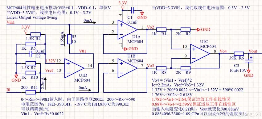
6) Linear output voltage swing: VSS+0.1 ~ VDD–0.1, unit is V.
When the power supply voltage is 3.3V, the linear output voltage swing is 0.1~3.2V. In order to ensure that the amplified signal works in the linear region, when VDD=3.3V, we set the MCP604 output voltage to remain at: 0.5V ~ 2.5V to meet the requirements of op amp circuit design.
The op amp in the analog electronics book is an ideal operational amplifier, which is different from the actual amplifier. Portanto, it is necessary to consider “input offset voltage”, “input bias current” e “linear output voltage swing” when designing.
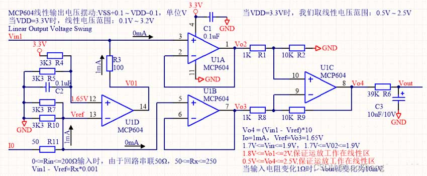
3. Circuit diagram
R11 in the figure is a bias circuit to prevent the last stage of differential amplifier output from saturation distortion.
1) Select a suitable amplification factor to reduce the output error. Because of the existence of input offset voltage, when the amplification factor increases, the output error will also increase, which must be considered in the design.
2) The amplification factor of this circuit is 10. Assuming the typical input offset voltage is 3mV, if the input signal changes to 5mV, 2mV will not be amplified, which will produce an output error of 20mV.
Vo4 = (Vin1 – Vref)*10
Io=1mA, Vref=Vo3=1.65V
1.7V<=Vin<=1.9V, 1.7V<=V02<=1.9
1.8V<=Vo1<=2V, ensure that the op amp works in the linear region, this is very important
0.5V<=Vo4<=2.5V, ensure that the op amp works in the linear region, this is why 50Ω is needed in series.
When the input resistance changes by 1Ω, Vout changes to 10mV. Since the input compensation voltage of MCP604 is ±3mV, when there is a change of 0.3333Ω, there will be a change of 3.333mV, and the acquisition sensitivity is high.
When 0<=Rin<=200Ω input, since the loop is connected in series with 50Ω, 50Oh<=Rx<=250Ω
Vin1 – Vref = Rx*0.001, unit A
4. Software calibration
New engineers always try to improve the accuracy of resistors, but the error is still large. Some engineers simply use continuously adjustable resistors, adjust their resistance values, and use multimeters to make the output meet the transfer relationship. This accuracy seems to be improved, but it is not convenient for production, and the difficulty of PCB design is also increased. Even if the debugging is done, if the adjustment screw is touched by hand, it may cause errors. The only way is to use fixed resistors for production and use software to help achieve accurate calibration.
1) When Rin=0, read a voltage value and record it as V50. Save V50, it will not change with the change of PT100 resistance value because it is powered by a constant current source.
2) Connect the nominal resistor, let Rs=100Ω, read a voltage value and record it as V150. Save V150, the voltage value read when the temperature is 0.
3) Calculate the current amplification factor: Io = (V150 – V50) / Rs; save Io, it means that the calibration is done.
4) When the input resistance is R, the voltage read is Vo, then R = (Vo- V50) / Io
Through the above description, software calibration has great advantages, not only convenient production, but also high accuracy. In order to improve the accuracy, the output voltage can also be divided into several intervals, calibrated separately, and different Io can be obtained, so that the output linearity will be better. These ideas are reflected in my design.
5. Calculate temperature
When the temperature is less than 0,
R0*C*t^4 – 100R0*C*t^3 + R0*B*t^2 + R0*A*t + R0 – Rt=0
When the temperature is greater than or equal to 0, Rt=R0*(1+A*t+B*t*t)
Descrição:
Rt is the resistance value of the platinum resistor at t℃
R0 is the resistance value of the platinum resistor at 0℃ 100Ω
A=3.9082×10^-3
B=-5.80195×10^-7
C=-4.2735×10^-12
6. Pt100 temperature sensor
Pt100 temperature sensor is a positive temperature coefficient thermistor sensor, and its main technical parameters are as follows:
1) Measurement temperature range: -200℃ ~ +850℃;
2) Allowable deviation value Δ℃: Grade A ±(0.15+0.002|t|), Grade B ±(0.30+0.005|t|);
3) Minimum insertion depth: The minimum insertion depth of the thermal resistor is ≥200mm;
4) Allowable current: < 5mA;
5) Pt100 temperature sensor also has the advantages of vibration resistance, boa estabilidade, alta precisão, and high pressure. Platinum thermal resistor has good linearity. When changing between 0 e 100 graus Celsius, the maximum nonlinear deviation is less than 0.5℃;
When temperature < 0, R0*C*t^4 – 100R0*C*t^3 + R0*B*t^2 + R0*A*t + R0 – Rt=0
When temperature ≥ 0, Rt= R0*(1+A*t+B*t*t)
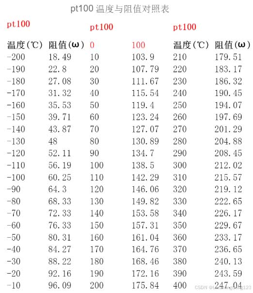
According to the above relationship, the approximate resistance range is: 18Ω~390.3Ω, -197℃ is 18Ω, 850Ω is 390.3Ω;
Descrição:
Rt is the resistance value of the platinum resistor at t℃, R0 is the resistance value of the platinum resistor at 0℃, 100Oh
A=3.9082×10^-3, B=-5.80195×10^-7, C=-4.2735×10^-12
PT100 platinum metal temperature sensor instruction manual
6) Circuit design
7) Relationship between PT100 temperature and resistance
PT100 temperature and resistance satisfy the following equation:
When temperature ≤0, R0*C*t^4 – 100*R0*C*t^3 + R0*B*t^2 + R0*A*t + R0 – Rt=0
When temperature ≥0, R0*B*t^2 + R0*A*t + R0 – Rt =0
Descrição:
Rt is the resistance value of the platinum resistor at t℃, R0 is the resistance value of the platinum resistor at 0℃, 100Oh
A=3.9082×10^-3, B=-5.80195×10^-7, C=-4.2735×10^-12
1. For the convenience of calculation, when the temperature is ≤0, let:
double a=R0*C*100000=100*(-4.2735×10^-12)*100000=-4.2735/100000
double b=–100*R0*C*100000=-100*100*(-4.2735×10^-12)*100000=4.2735/1000
double c= R0*B*100000=100*(-5.80195×10^-7)*100000=-5.80195
double d=R0*A*100000=100*(3.9082×10^-3)*100000=39082
double e= (100-Rt)*100000
When temperature ≤ 0, a*t^4 + b*t^3 + c*t^2 + d*t + e=0
where x3 is the solution of PT100 when it is less than 0℃.
2. For ease of calculation, when the temperature is greater than or equal to 0
double a= R0*B*100000=100*(-5.80195×10^-7)*100000=-5.80195
double b=R0*A*100000=100*(3.9082×10^-3)*100000=39082
double c= (100-Rt)*100000
When the temperature is ≥0, a*t^2 + b*t + c =0
t = [ SQRT( b*b – 4*a*c )-b ] / 2 / um
19.785Ω corresponds to -197℃, the temperature of liquid nitrogen
18.486Ω corresponds to -200℃
96.085Ω corresponds to -10℃
138.505Ω corresponds to 100℃
175.845Ω corresponds to 200℃
247.045Ω corresponds to 400℃
 English
 العربية
 Български
 粤语
粤语 中文(简体)
 中文(漢字)
 Nederlands
 Suomi
Suomi Français
 Deutsch
 Ελληνικά
 Magyar
 Italiano
 日本語
日本語 한국어
한국어 Polski
 Português
 Română
 Русский
 Slovenščina
 Español
 Svenska
 ภาษาไทย
 Türkçe
 Tiếng Việt

