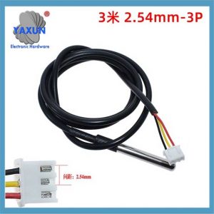
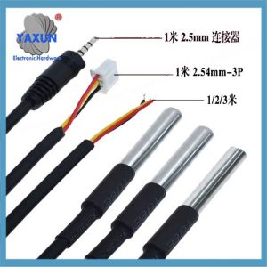
Introduction: This article explains in detail the application of custom DS18B20 digital temperature sensor in building a digital thermometer. Including working principle, hardware connection, software programming and simulation implementation. Provide complete protues simulation diagram, C source code and result analysis to help readers deeply understand and practice the use of DS18B20.
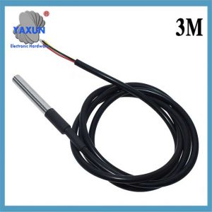
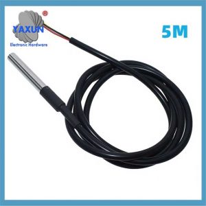
Parameter information: источник питания: 3.0В – 5.5В; Adjustable resolution: 9 – 12 кусочек; Температурная диапазон: -55 ℃ to +125 ℃; Выход : red (VCC), yellow (DATA), black (Земля);
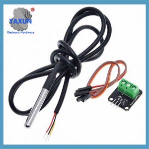
What you get: you will get 4 DS18B20 temperature sensors, 4 adapter modules and 4 female to female jumper wires; The adapter module has a pull-up resistor, which can be compatible with Raspberry Pi without an external resistor;
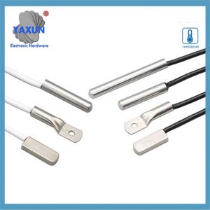
DS18B20 temperature sensor: the size of stainless steel housing is approx. 6 х 50 mm/ 0.2 х 2 дюйм, and the digital temperature thermal cable has a total length of approx. 1 m/ 39.4 дюйм, which is long enough to meet your needs;
Quality material: the probe is made of quality stainless steel material, which is waterproof, moisture-proof and not easy to rust, so as to prevent short circuits;
Wide application: this DS18B20 temperature sensor is compatible with Raspberry Pi, and is widely applied in temperature monitoring of cable trench, boiler, zer, agricultural greenhouse, clean room, и т. д..
1. DS18B20 sensor characteristics
The DS18B20 sensor plays a key role in the field of modern temperature monitoring. It can measure temperature with high accuracy, and its resolution can be adjusted according to needs, so as to achieve temperature monitoring with different degrees of precision. Кроме того, the small size of DS18B20 makes it suitable for use in environments with limited space, and its easy-to-use characteristics reduce the technical threshold from beginners to professionals.
Before further exploring the performance parameters of DS18B20, it is necessary to first understand its working principle. DS18B20 communicates temperature data through digital signals, which brings convenience to the collection of temperature data. Compared with traditional analog temperature sensors, digital sensors such as DS18B20 can provide more accurate readings and are less sensitive to noise during signal transmission.
In order to fully utilize these advantages of DS18B20, we must have a deep understanding of its performance parameters. These parameters include temperature measurement range, точность, resolution, and supply voltage. These parameters not only determine whether DS18B20 can meet the needs of specific applications, but also affect the performance and reliability of the entire system.
In this chapter, we will introduce the performance parameters of DS18B20 in detail, analyze its working principle, and explore its advantages in different applications. Through these contents, readers will gain a deeper understanding of DS18B20 sensors and lay a solid foundation for subsequent more complex applications and programming.
2. Detailed explanation of DS18B20’s 1-Wire communication protocol
The reason why DS18B20 sensors are widely used is largely due to its unique communication protocol – 1-Wire communication protocol. This protocol simplifies the requirements for hardware connections and provides an efficient way to transmit data. This chapter will deeply analyze the working mechanism and data exchange process of the 1-line communication protocol to lay a solid foundation for subsequent programming practice.
2.1 Basics of 1-Wire Communication Protocol
2.1.1 Features of 1-Wire Communication Protocol:
DS18B20 1-Wire Communication Protocol is also called “single bus” technology. It has the following features: – Single bus communication: Only one data line is used for bidirectional data transmission, which greatly reduces the complexity of wiring compared to the traditional multi-wire sensor communication method. – Multi-device connection: Supports connecting multiple devices on one data bus, and identifies and communicates through device identification codes. – Low power consumption: During communication, the device can be in a low-power standby state when not participating in communication. – Высокая точность: With a shorter data transmission time, it can reduce external interference and improve data accuracy.
2.1.2 Data format and timing analysis of 1-wire communication
The data format of the 1-wire communication protocol follows a specific timing rule. It includes initialization timing, write timing and read timing:
Initialization timing: The host first starts the presence detection timing (Presence Pulse) by pulling down the bus for a certain period of time, and the sensor then sends a presence pulse in response.
Write timing: When the host sends a write timing, it first pulls down the bus for about 1-15 микросекунд, then releases the bus, and the sensor pulls down the bus in 60-120 microseconds to respond.
Read timing: The host notifies the sensor to send data by pulling down the bus and releasing it, and the sensor will output the data bit on the bus after a certain delay.
3. Thermometer Hardware Connection Method
Hardware connection is the first and most important step in building a digital thermometer. The correct connection between the DS18B20 sensor and the microcontroller will ensure accurate data transmission and provide a solid foundation for further software programming and data processing. This chapter will introduce in detail the interface design principles between DS18B20 and microcontroller and the specific steps of circuit connection, and cover the relevant content of power supply and signal conditioning.
3.1 Interface between DS18B20 and microcontroller
3.1.1 Interface circuit design principles
The interface circuit design of DS18B20 needs to follow several core principles to ensure stable and efficient operation of the device:
Stable power supply: DS18B20 can obtain power from the data line “DQ” (called “parasitic power mode”), or it can be independently powered by an external power supply. Regardless of which method is used, the power supply must be stable to prevent data transmission errors caused by power supply fluctuations.
Signal integrity: Since DS18B20 transmits data through a single line, signal integrity is particularly critical. It is necessary to consider the anti-interference ability of the signal and the matching of the electrical characteristics of the signal.
Circuit protection: Overcurrent protection and electrostatic discharge (ESD) protection measures should be included in the circuit design to avoid damage to the sensor or microcontroller.
3.1.2 Specific steps for circuit connection
Connecting DS18B20 to a microcontroller usually follows the following steps:
Подключение к питанию: Connect the VDD pin of DS18B20 to a 3.3V or 5V power supply (depending on the voltage level of the microcontroller), and the GND pin to the ground line.
Data line connection: The DQ pin is connected to a digital I/O pin of the microcontroller. In order to ensure the stability of data transmission, a pull-up resistor can be added between the data line and the power supply, with a typical value of 4.7kΩ to 10kΩ.
Reset and presence pulse pin processing: Normally, the reset pin (РСТ) and presence pulse pin (PAR) of DS18B20 do not need to be connected externally, they are internally used signals.
In this section, we designed a basic circuit through which the DS18B20 temperature sensor can be connected to a microcontroller. The following is an example circuit diagram based on Arduino Uno and the corresponding description:
flowchart LR
ДС18Б20 — |VDD| 5В
ДС18Б20 — |Земля| Земля
ДС18Б20 — |DQ| 2
DQ — |Pull-up| 5В
Среди них, DS18B20 represents the digital temperature sensor, 5V is the power output of the microcontroller, GND is the ground wire, и 2 represents the Arduino’s pin No. 2, which is used for data transmission. The connection between DQ and 5V represents the pull-up resistor.
3.2 Power supply and signal conditioning
3.2.1 Choice of power supply method
DS18B20 provides two power supply methods:
Parasitic power mode: In this mode, the data line (DQ) can not only transmit data, but also power the DS18B20. В это время, the high-level voltage on the data line should be at least 3.0V to ensure sufficient power supply current. This mode is usually used when the bus length is short and data transmission is not too frequent.
External power supply mode: In this mode, DS18B20 has an independent power input VDD. Powering with an external power supply can enhance the signal strength of the sensor and improve anti-interference ability, which is suitable for long-distance transmission or frequent data transmission.
3.2.2 Signal filtering and stabilization
In order to ensure signal stability and accurate data reading, the signal needs to be properly filtered and stabilized:
Pull-up resistor: The pull-up resistor is added between the data line and the power supply to ensure that the data line is in a high-level state when idle.
De-jitter circuit: In order to eliminate erroneous readings caused by line interference or instantaneous voltage fluctuations, the signal can be software-de-jittered on the microcontroller side.
ESD protection: ESD protection components (such as TVS diodes) are added to the ports of sensors and microcontrollers to prevent damage caused by electrostatic discharge.
This section further elaborates on the factors that should be considered when selecting power supply and signal conditioning in table form:
| Project | Parasitic power mode | External power mode | Описание | | — | — | — | — | | Applicable scenarios | Short lines, infrequent data | Long lines, frequent data | Select according to actual application scenarios | | Power supply stability | Lower | Higher | External power supply is recommended for long lines or high frequencies | | Расходы | Lower | Higher | External power supply requires additional power management components | | Anti-interference | Weaker | Stronger | External power supply is more suitable for high-interference environments |
The above connection methods and signal processing strategies can effectively integrate the DS18B20 temperature sensor into any microcontroller system. The next chapter will introduce how to use C language to:
Functional programming practice of DS18B20:
4. DS18B20 digital thermometer C language programming
4.1 Programming foundation and environment preparation
4.1.1 Program design ideas and framework construction
Before starting to write the C language program of the DS18B20 digital thermometer, you first need to establish the basic ideas of program design. The DS18B20 sensor communicates with the microcontroller through the 1-wire communication protocol. Поэтому, the main task of the program is to implement the related operations of the 1-wire communication protocol, including initializing DS18B20, sending instructions, reading temperature data, and converting and displaying the read data.
The program framework is roughly divided into the following parts:
Initialization: Initialize the microcontroller and DS18B20 sensor.
Main loop: Contains a loop that continuously reads sensor data.
1-wire communication function library: Contains functions for implementing the one-wire communication protocol.
Data processing: Convert the raw data returned by the sensor into readable temperature values.
Display output: Display the processed temperature data on the LCD screen or output it to the computer through the serial port.
4.1.2 Development environment construction and configuration
In order to program and develop the DS18B20 digital thermometer, you need to prepare the development environment and configure it appropriately. The following are the basic steps for development:
Select the development environment: Select the appropriate integrated development environment (IDE) according to the type of microcontroller, such as for development based on the ARM Cortex-M series microcontroller. You can use Keil MDK or STM32CubeIDE.
Configure the compiler: According to the IDE used, configure the compiler to ensure that the C language code can be compiled correctly.
Build the hardware development board: Select a suitable microcontroller development board, such as based on STM32, ESP32, и т. д..
Connect the development board: Connect the DS18B20 sensor to the specified pin of the microcontroller through the 1-wire communication protocol.
Write code: Create a new C language project in the IDE and start writing program code.
Compile and debug: Use the IDE tool to compile the code and run it on the development board for debugging.
#include <stdio.h>
// DS18B20 first-line communication function library declaration
void DS18B20_Init();
void DS18B20_Reset();
void DS18B20_WriteByte(unsigned char dat);
unsigned char DS18B20_ReadByte();
int DS18B20_ReadTemperature();
int main() {
// Initialize DS18B20 sensor
DS18B20_Init();
// Main loop
пока(1) {
// Read temperature value
int temperature = DS18B20_ReadTemperature();
// Output temperature value to serial port or other display device
printf(“Current temperature: %d\n”, температура);
}
return 0;
}
4.2 DS18B20 temperature reading program implementation
4.2.1 Construction of the one-wire communication function library
In order to realize the temperature reading of DS18B20, you first need to build a one-wire communication function library. The following are the implementation methods of several key functions:
DS18B20_Init(): Initialize the one-wire communication timing.
DS18B20_Reset(): Reset the sensor and detect its pulse.
DS18B20_WriteByte(unsigned char dat): Write a byte of data to the sensor.
DS18B20_ReadByte(): Read a byte of data from the sensor.
DS18B20_ReadTemperature(): Read the temperature and convert it.
The implementation of the one-wire communication function library of DS18B20 is quite complicated because it requires precise control of the pin level changes to follow the one-wire communication protocol. The following is an example of a function implementation:
void DS18B20_Reset() {
// One-line communication reset sequence, including pulling down the data line, delay, releasing the bus, and detecting the presence pulse
// …
}
The purpose of this function is to send a reset pulse to the DS18B20. After the reset is successful, the DS18B20 will return a presence pulse.
4.2.2 Implementation of the temperature reading algorithm
Reading the temperature value of the DS18B20 sensor is a more complicated process, because it is necessary to send specific instructions to the sensor in a certain timing and read the returned data correctly. The algorithm for reading the temperature value is as follows:
Reset the sensor.
Send the “skip ROM” command (0xCC).
Send the “convert temperature” command (0x44).
Wait for the conversion to complete.
Send the “read register” command (0xBE).
Read two bytes of temperature data.
The following code shows how to read the temperature value of the DS18B20:
int DS18B20_ReadTemperature() {
unsigned char temp_low, temp_high;
unsigned int temp;
// Reset the sensor and skip ROM instructions
DS18B20_Reset();
DS18B20_WriteByte(0xCC); // Skip ROM commands
// Send conversion temperature command
DS18B20_WriteByte(0x44);
// Wait for the conversion to complete. Here you need to wait according to the conversion time of DS18B20
// …
// Reset the sensor and read the temperature data
DS18B20_Reset();
DS18B20_WriteByte(0xCC); // Skip ROM commands
DS18B20_WriteByte(0xBE); // Read register command
// Read two bytes of data
temp_low = DS18B20_ReadByte();
temp_high = DS18B20_ReadByte();
// Combine two bytes of data into a 16-bit integer
Temp = (temp_high << 8) | temp_low;
// Return the temperature value, converting appropriately based on the resolution of the DS18B20
return temp;
}
4.2.3 Program debugging and exception handling
When writing a DS18B20 reading program, program debugging and exception handling are very important. During debugging, you may need to use the serial port debugging assistant to check whether the output temperature value is correct, or use a logic analyzer to monitor the signal timing of the first-line communication. Exception handling needs to take into account hardware failures, communication errors, and abnormal responses of DS18B20.
The following are some debugging and exception handling strategies:
Data verification: After each data read, use a checksum or check bit to confirm the correctness of the data.
Exception capture: Add an exception capture mechanism to the program, such as a timeout retry mechanism, reset the sensor, и т. д..
Debug information: Add sufficient debugging information output to the program to help locate the problem.
int main() {
// Initialize DS18B20 sensor
DS18B20_Init();
// Main loop
пока(1) {
int temperature;
// Read temperature and check for errors
temperature = DS18B20_ReadTemperature();
если (температура < 0) {
printf(“Error reading temperature!\n”);
// You can choose to retry or other error handling mechanisms
} else {
printf(“Current temperature: %d\n”, температура);
}
}
return 0;
}
This chapter introduces the C language programming foundation and environment preparation of the DS18B20 digital thermometer, as well as the implementation of the temperature reading program, and emphasizes the importance of program debugging and exception handling. Through the introduction of this chapter, readers should be able to build a development environment, understand the importance of the first-line communication function library, and write a basic temperature reading program. The following chapters will further delve into the construction and use of the Proteus simulation environment, providing a simulation test method for actual hardware assembly.
5. Proteus simulation diagram and simulation result analysis
5.1 Proteus simulation environment construction
5.1.1 Basic operation of Proteus software
Before starting to build the simulation model of the DS18B20 digital thermometer, you first need to understand and master the basic operation of Proteus software. Proteus is a powerful electronic circuit simulation software that can not only design circuit schematics, but also design circuit PCB layouts and provide simulation functions. Here are some key steps to help you get started with Proteus:
Open the Proteus software and create a new project.
Search and select the required components in the component library, such as DS18B20 sensors, microcontrollers, источники питания, connecting wires, и т. д..
Drag the selected components to the design area and use the mouse to place and layout them.
Use the wiring tool to connect the pins of each component to form a complete circuit.
Double-click a component or wire to modify its properties, such as resistance value, power supply voltage, и т. д..
Make sure all components are connected correctly and check for errors or omissions.
5.1.2 Create a DS18B20 simulation project
The steps to create a simulation project for the DS18B20 digital thermometer are as follows:
Start Proteus and select “New Project” to create a new project.
After setting the project name and location, click “Следующий”.
Select a project template, такой как “Microprocessor Based”, and click “Следующий”.
In the “Project Items” tab, check “Include default components” and select a microcontroller (such as PIC, AVR, и т. д.) and a DS18B20 sensor.
Click “Finish” to complete the project creation.
Следующий, create a circuit schematic:
Select the “PICK DEVICE” tool, find and select the microcontroller and DS18B20 sensor in the component library.
Use the “PLACE DEVICE” tool to place the selected component in the design area.
Use the “ПРОВОЛОКА” tool to connect the microcontroller and the relevant pins of the DS18B20 sensor.
After completing the connection, use the “ТЕКСТ” tool to add annotations to the circuit diagram for easy understanding and modification.
5.2 Simulation test and data analysis
5.2.1 Set simulation parameters and conditions
Before starting the simulation, you need to set the parameters and conditions for the simulation run:
Double-click the microcontroller component to enter the property setting interface.
Select the previously written program file path at “Program File”.
Set the power supply parameters to ensure that both the microcontroller and the DS18B20 sensor have the correct power supply voltage.
Следующий, set the time parameters for the simulation:
In the simulation control panel, select “Global Settings”.
Adjust the simulation speed and maximum simulation time.
Set appropriate breakpoints to analyze data during the simulation process.
5.2.2 Simulate and read temperature data
Run the simulation and simulate temperature data:
Click the “Play” button in the simulation control panel to start the simulation.
Use the “DEBUG” tool to view the program running status and variable values.
Simulate the DS18B20 sensor to read the temperature value, which is usually achieved by modifying the virtual thermometer in the simulation environment.
To read temperature data in the simulation, you can refer to the following steps:
Find the temperature simulation settings in the properties of the DS18B20 component.
Modify the temperature value to test the system response under different temperature conditions.
Observe how the microcontroller program processes the temperature data.
5.2.3 Result Analysis and Troubleshooting
Analyze the simulation results and confirm the performance of the thermometer:
Monitor the data in the output window to check whether the temperature reading is accurate.
Use the logic analyzer tool to monitor whether the data communication process is normal.
Check for any abnormal signals or unstable outputs.
Perform fault diagnosis and debugging:
If the temperature reading is inaccurate or there is an error, check the connection method and configuration of the DS18B20.
Analyze the program code to ensure that the first-line communication and data conversion algorithms are implemented correctly.
Use the “Stop” function of the simulation software to pause the simulation and observe the current status of the system.
 English
 العربية
 Български
 粤语
粤语 中文(简体)
 中文(漢字)
 Nederlands
 Suomi
Suomi Français
 Deutsch
 Ελληνικά
 Magyar
 Italiano
 日本語
日本語 한국어
한국어 Polski
 Português
 Română
 Русский
 Slovenščina
 Español
 Svenska
 ภาษาไทย
 Türkçe
 Tiếng Việt

