English
 العربية
 Български
 粤语
粤语 中文(简体)
 中文(漢字)
 Nederlands
 Suomi
Suomi Français
 Deutsch
 Ελληνικά
 Magyar
 Italiano
 日本語
日本語 한국어
한국어 Polski
 Português
 Română
 Русский
 Slovenščina
 Español
 Svenska
 ภาษาไทย
 Türkçe
 Tiếng Việt


Sensor probe and cable is the packaging form of the sensor, which is the most basic unit of the sensor. The sensor is packaged through a reasonable electronic circuit and external packaging structure. It has some independent functional components we need. Как и датчик, обычно делится на: Термисторный зонд NTC, Зонд PT100, Зонд PT1000, Зонд Дс18б20, датчик температуры воды, автомобильный датчик-зонд, Зонд RTD, датчик контроля температуры, датчик регулировки температуры, датчик датчика бытовой техники, и т. д..
|
Ds18b20 sensor probe with cable |
Temperature control probe with cable |
PT100 temperature sensor probe with cable |
A NTC probe structure based on temperature prediction and its temperature measurement method, the probe includes: multiple NTC probes; copper shell; metal support structure, wire and heat conductor.
Step 1, among m NTC probes, obtain the temperatures T0, T1, …, Tn measured at equal time intervals through each NTC probe, where n represents the serial number of the collected temperature;
Step 2, calculate the temperature difference vn=TnTn1 collected at adjacent temperature measurement times;
Step 3, calculate the parameter α=vn/vn1;
Step 4, calculate the predicted temperature Tp=Tn1+vn/(1α) of a single probe;
Step 5, calculate the measured temperature Tb. The present invention can further reduce the error and has good general applicability.
Full analysis of thermistors!
🤔 Do you know what a thermistor is? It is a little expert in electronic circuits!
👍 Thermistors, in simple terms, are a type of sensitive element that can adjust its resistance value according to temperature changes.
🔥 Positive temperature coefficient thermistor (ПТК), Когда температура повышается, its resistance value will increase significantly. This feature makes it shine in automatic control circuits!
|
Water temperature sensor probe with cable |
Зонд для барбекю, датчик NTC для духовки с кабелем |
Датчик NTC и кабель |
❄️ The negative temperature coefficient thermistor (НТЦ) is the opposite, with the resistance decreasing when the temperature rises. В бытовых приборах, it is often used for soft start, automatic detection and control circuits.
💡 Now you have a deeper understanding of thermistors! In the electronic world, it is an indispensable role!
1. Introduction to NTC
NTC thermistor is a thermistor named after the acronym of Negative Temperature Coefficient. Обычно, the term “термистор” refers to NTC thermistors. It was discovered by Michael Faraday, who was studying silver sulfide semiconductors at the time, in 1833, and commercialized by Samuel Reuben in the 1930s. NTC thermistor is an oxide semiconductor ceramic composed of manganese (Mn), никель (В) and cobalt (Co).
It can be seen everywhere in our lives. Due to the characteristic that the resistance decreases with the increase of temperature, it is not only used as a temperature sensing device in thermometers and air conditioners, or a temperature control device in smartphones, kettles and irons, but also used for current control in power supply equipment. Recently, as the degree of vehicle electrification increases, thermistors are increasingly being used in automotive products.
2. Working Principle
В целом, the resistance of metals increases as the temperature increases. This is because heat intensifies the lattice vibration, and the average moving speed of free electrons decreases accordingly.
In contrast, the proportion of free electrons and holes in semiconductors increases due to heat conduction, and this part is greater than the proportion of the part where the speed decreases, so the resistance value decreases.
Кроме того, due to the existence of the band gap in semiconductors, when externally heated, electrons in the valence band move to the conduction band and conduct electricity. In other words, the resistance value decreases as the temperature increases.
3. Basic characteristics
3.1 Resistance-temperature characteristics (R-T characteristics)
The resistance value of an NTC thermistor is measured at a current with sufficiently low self-heating (heat generated due to the applied current). As a standard, it is recommended to use the maximum operating current. And, the resistance value needs to be expressed in pairs with the temperature.
The characteristic curve is described by the following formula:
R0, Р1: resistance value at temperature T0, T1
T0, T1: absolute temperature
Б: Б постоянен
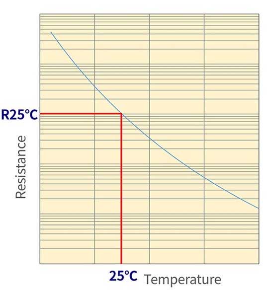
R-T Characteristics of NTC Thermistors
Figure 1: R-T characteristic of NTC thermistor
3.2 Б постоянен
The B constant is a single value that characterizes the NTC thermistor. Adjustment of the B constant always requires two points. The B constant describes the slope of the two points.
If the two points are different, the B constant will also be different, so please pay attention when comparing. (See Figure 2)
The horizontal axis is the temperature characteristic of 1-T
Figure 2: Different B constants selected at 2 points
Из этого, it can be seen that B is the slope of the lnR vs. 1/T curve:
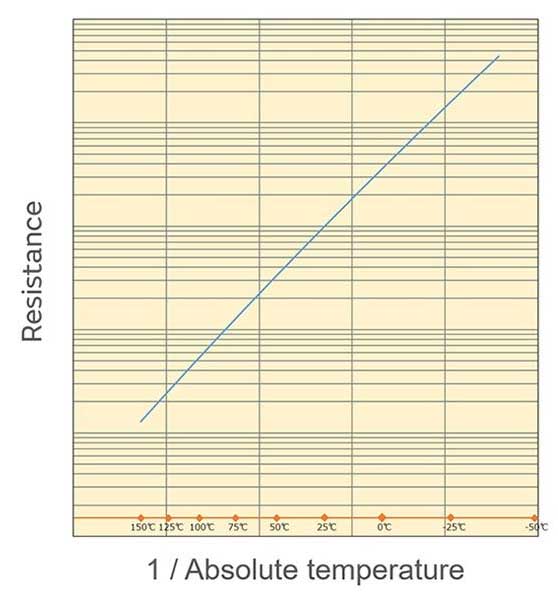
Murata uses 25°C and 50°C to define the B constant, written as B (25/50).
As shown in Figure 3, 1/Т (T is absolute temperature) is in logarithmic proportion to the resistance value. It can be seen that the relationship is close to a straight line.
V-I Characteristics of NTC Thermistors
Figure 3: Temperature characteristics with 1/T as the horizontal axis
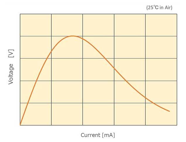
3.3 Volt-ampere characteristics (V-I characteristics)
The V-I characteristics of NTC thermistors are shown in Figure 4.
Thermal dissipation constant per unit element
Figure 4: V-I characteristics of NTC thermistors
In the area with low current, the voltage of the ohmic contact gradually increases as the current gradually increases. The self-heating caused by the flow of current does not cause the temperature of the resistor to rise by dissipating heat from the surface of the thermistor and other parts.
Однако, when the heat generation is large, the temperature of the thermistor itself rises and the resistance value decreases. In such an area, the proportional relationship between current and voltage no longer holds.
В целом, thermistors are used in an area where the self-heating is as low as possible. As a standard, it is recommended that the operating current be kept below the maximum operating current.
If used in an area exceeding the voltage peak, thermal runaway reactions such as repeated heating and reduced resistance may occur, causing the thermistor to turn red or break. Please avoid using it in this range.
3.4 Temperature coefficient of resistance (α)
The rate of change of the NTC thermistor per unit temperature is the temperature coefficient, which is calculated by the following formula.
Example: When the temperature is close to 50°C and the B constant is 3380K
α = −3380/(273.15 + 50)² × 100 [%/°С] = −3.2 [%/°С]
Поэтому, the temperature coefficient of resistance is as follows.
Thermal Time Constant of NTC Thermistor
α = − B/T² × 100 [%/°С]
3.5 Thermal dissipation constant (δ)
When the ambient temperature is T1, when the thermistor consumes power P (МВт) and its temperature changes to T2, the following formula holds.
P = δ (T2 − T1)
δ is the thermal dissipation constant (mW/°C). The above formula is transformed as follows.
NCU15 maximum voltage derating
δ = P/ (T2 − T1)
The thermal dissipation constant δ refers to the power required to increase the temperature by 1°C under self-heating conditions.
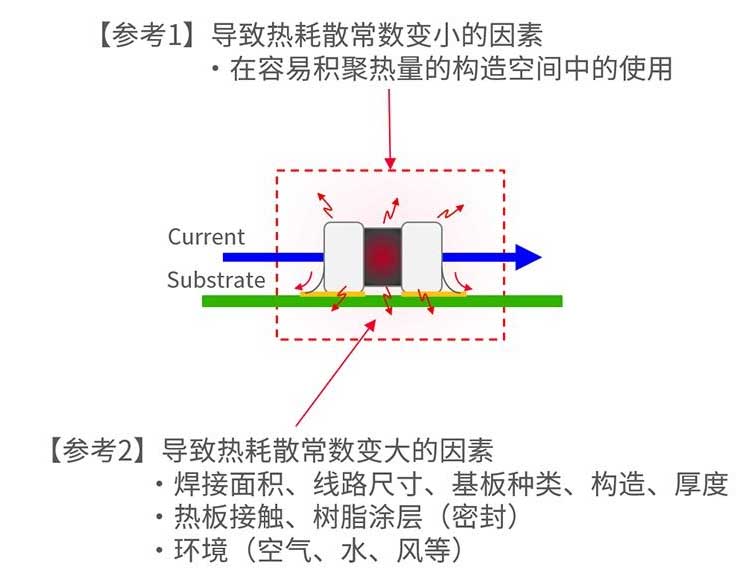
The thermal dissipation constant δ is determined by the balance between “self-heating due to power consumption” и “heat dissipation”, and therefore varies significantly depending on the thermistor’s operating environment.
Maximum operating current (Iop), maximum operating voltage (Vop)
Murata defined the concept of “thermal dissipation constant per unit element”.
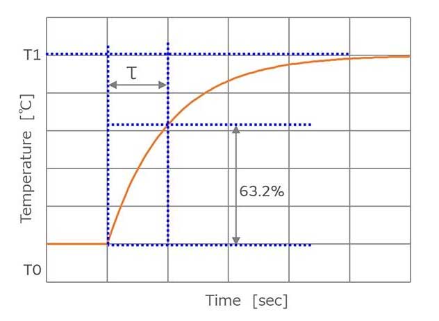
3.6 Thermal time constant (τ)
When a thermistor maintained at temperature T0 is suddenly changed to ambient temperature T1, the time it takes to change to the target temperature T1 is called the thermal time constant (τ). Обычно, this value refers to the time required to reach 63.2% of the temperature difference between T0 and T1.
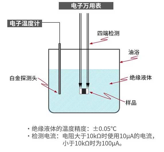
Murata’s resistance value measurement method
When a thermistor maintained at one temperature (T0) is exposed to another temperature (T1), the temperature changes exponentially, and the temperature (Т) after the elapse of time (t) is expressed as follows.
Т = (T1 − T0) (1 − exp (−t/τ) ) + T0
Take t = τ,
Т = (T1 − T0) (1−1/e) + T0
(T − T0)/(T1 − T0) = 1 − 1/e = 0.632
That is why τ is specified as the time to reach 63.2% of the temperature difference.
Figure 6: Thermal time constant of NTC thermistor
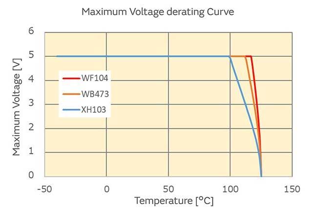
3.7 Максимальное напряжение (Vmax)
The maximum voltage that can be directly applied to the thermistor. When the applied voltage exceeds the maximum voltage, the product performance will deteriorate or even be destroyed.
Кроме того, the temperature of the component rises due to self-heating. It is necessary to pay attention that the temperature of the component does not exceed the operating temperature range.
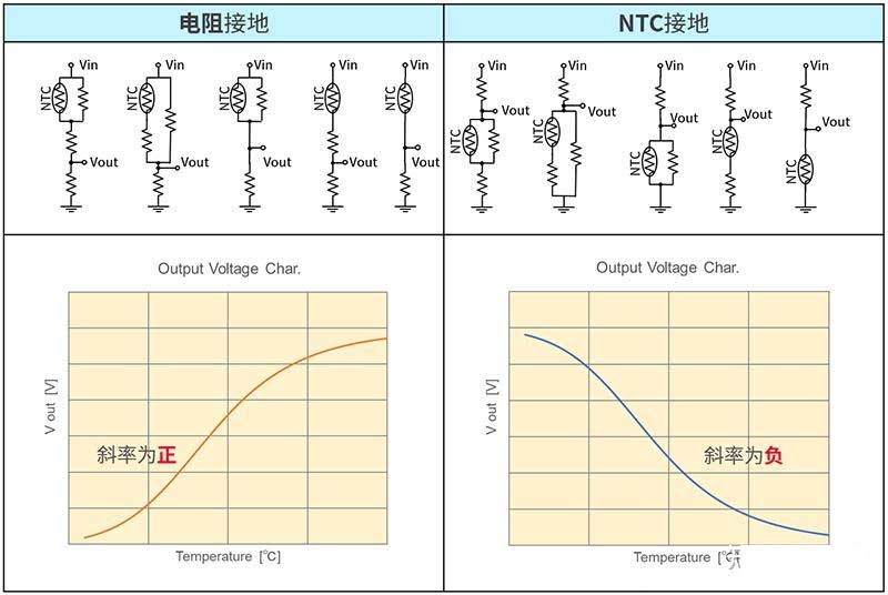
Output characteristics of resistor-grounded and thermistor-grounded circuits
Figure 7: Maximum voltage derating for NCU15 type
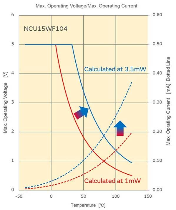
3.8 Maximum operating current (Iop), maximum operating voltage (Vop)
Murata defines the maximum operating current and maximum operating voltage as the current and voltage at which self-heating is 0.1℃ when applied. With reference to this value, thermistors can achieve more accurate temperature measurement.
Поэтому, applying current/voltage exceeding the maximum operating current/voltage does not cause thermistor performance degradation. Однако, please note that self-heating of the component will cause detection errors.
How Murata calculates the maximum operating current
When calculating the maximum operating current, the thermal dissipation constant (1mW/°C) defined by the unit component is required. The thermal dissipation constant indicates the degree of heat dissipation, but the heat dissipation state varies greatly depending on the working environment.
The working environment includes the material, толщина, структура, soldering area size, hot plate contact, resin packaging, и т. д.. of the substrate. The use of the unit component definition eliminates environmental interference factors.
According to experience, the thermal dissipation constant in actual use is about 3 к 4 times that of the unit component. Assuming that the actual thermal dissipation constant is 3.5 раз, the maximum operating current is shown in the blue curve in the figure. Compared with the case of 1mW/°C, it is now 1.9 раз (√3.5 times).
3.9 Zero load resistance value
The resistance value measured at a current (voltage) where self-heating is negligible. As a standard, it is recommended to use the maximum operating current.
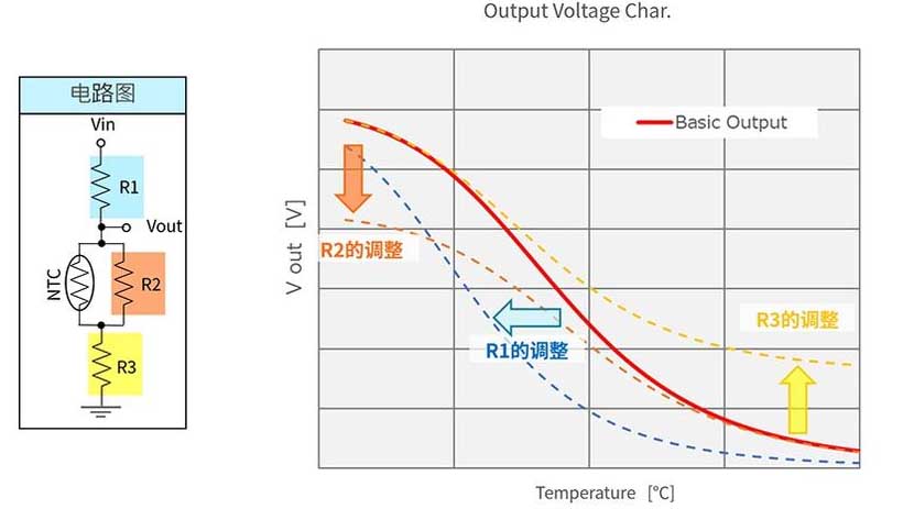
Adjustment of R value and change of output characteristics
Figure 9: Murata’s resistance value measurement method
4. How to use
4.1 Circuit diagram
The output voltage may vary depending on the NTC thermistor wiring diagram. You can simulate it at the following URL on the Murata official website.
SimSurfing: NTC Thermistor Simulator (murata.co.jp)
Figure 10 Output characteristics of resistor grounding and thermistor grounding circuits
4.2 Adjustment of R1 (voltage divider resistor), Р2 (parallel resistor), Р3 (series resistor)
The output voltage may vary according to the circuit diagram.
Figure 11 Adjustment of R value and change of output characteristics
4.3 Calculation of detection error using Murata’s official tool
Select the relevant parameters of the NTC thermistor and the relevant parameters of the voltage divider circuit (reference voltage and voltage divider resistor, resistance accuracy), and then the error curve of temperature detection can be generated normally, Как показано на рисунке ниже:
Figure 12 Generating temperature detection error curve using official tools
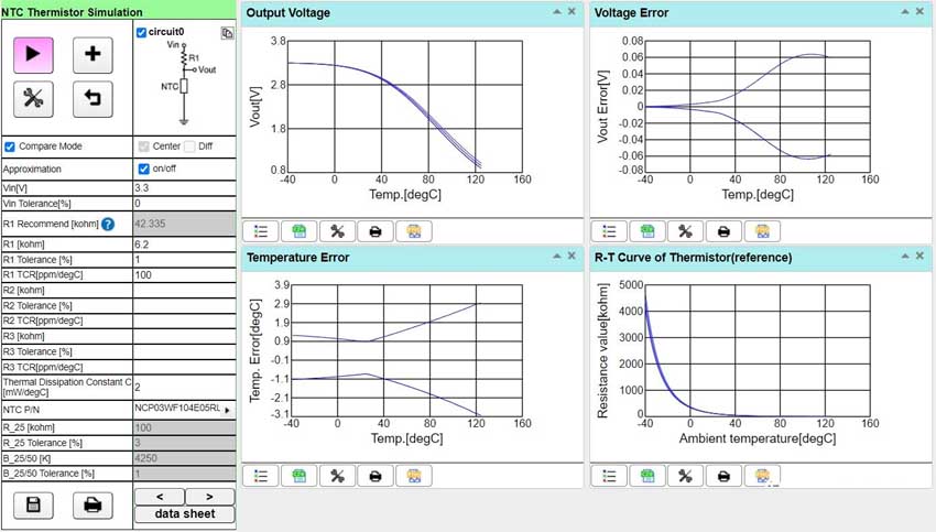
Tool generates temperature sensing NTC thermistor error curve