2-žica, 3-wire or 4-wire Pt100, Pt500, Pt1000 sensors are temperature sensors based on platinum elements with high accuracy, stability and linearity, and are widely used in fields that require accurate temperature measurement. A “PT100 thermal resistor temperature measurement system” refers to a system that uses a PT100 sensor, a type of Resistance Temperature Detector (RTD), to measure temperature by detecting changes in its electrical resistance which are directly proportional to the temperature; “PT” stands for Platinum, in “100” indicates that the sensor has a resistance of 100 ohms at 0°C making it a highly accurate and stable method for temperature measurement across a wide range.
Platinasti upori se pogosto uporabljajo v srednjem temperaturnem območju (-200~650 ℃). Trenutno, na trgu so standardni toplotni upori za merjenje temperature iz kovinske platine, kot je Pt100, Pt500, Pt1000, itd.
Understand the working principle of PT100: PT100 is a temperature sensor of Pt resistor. The working principle is based on the thermal effect of resistor. Its resistance value changes with the change of temperature. This change is linear. At 0℃, the resistance value of PT100 is 100 ohms. As the temperature rises, the resistance value also increases accordingly, so the temperature can be accurately inferred by measuring the resistance value.
Choose the appropriate wiring method: Na splošno, 2-žica, 3-wire or 4-wire wiring methods can be used.
Key points about a PT100 system:
Sensor principle:
The PT100 sensor is made of a platinum wire whose electrical resistance changes predictably with temperature fluctuations.
Measurement method:
When a current is passed through the PT100, the voltage drop across the sensor is measured, which is then converted to temperature based on the known relationship between resistance and temperature.
Široka uporaba:
PT100 sensors are commonly used in industrial processes, laboratories, and other applications where precise temperature measurement is required due to their high accuracy and stability.
Components of a PT100 system:
Senzor PT100:
The actual sensing element, typically a platinum wire wrapped around a ceramic core, which is inserted into the environment to be measured.
Signal conditioning circuitry:
Electronics that amplify and convert the small resistance change from the PT100 into a measurable voltage signal.
Display or data acquisition system:
Device that displays the measured temperature or stores the data for analysis.
Benefits of using a PT100 system:
Visoka natančnost: Considered one of the most accurate temperature sensors available.
Široko temperaturno območje: Can measure temperatures from -200°C to 850°C depending on the sensor design.
Dobra linearnost: The relationship between resistance and temperature is very linear, making for easy data interpretation.
Stabilnost: Platinum is a very stable material, ensuring consistent readings over time.
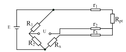
The three wiring methods of PT100 platinum resistor are different in principle: 2-wire and 3-wire are measured by bridge method, and the relationship between temperature value and analog output value is given in the end. 4-wire has no bridge. It is completely sent by constant current source, measured by voltmeter, and finally gives the measured resistance value, which is difficult and costly to use.
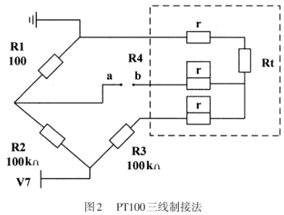
Because PT100 has a small resistance value and high sensitivity, the resistance value of the lead wire cannot be ignored. The use of 3-wire connection can eliminate the measurement error caused by the lead line resistance.
The 2-wire system has poor measurement accuracy; the 3-wire system has better accuracy; the 4-wire system has high measurement accuracy, but requires more wires.
We only need to know the temperature state of PT100 based on the voltage signal output by the bridge. When the resistance value of PT100 is not equal to the resistance value of Rx, the bridge outputs a differential pressure signal, which is very small. Since the output signal of the temperature sensor is generally very weak, a signal conditioning and conversion circuit is required to amplify it or convert it into a form that is easy to transmit, process, record and display. The slight change in the measured signal quantity needs to be converted into an electrical signal. When amplifying the DC signal, the self-drift and unbalanced voltage of the op amp cannot be ignored when passing through the op amp. After amplification, a voltage signal of the desired size can be output.
The resistance value of the platinum resistor can be obtained by circuit calculation or multimeter measurement. When we know the resistance value of PT100, we can measure and calculate the temperature by the resistance value.
Use appropriate algorithms for data processing: Use the known temperature and resistance relationship to calculate the temperature through programming. Considering that the resistance-temperature relationship of PT100 is nonlinear, especially in low or high temperature areas, more complex algorithms may be needed to improve accuracy.
Impact of environmental factors: Performance may be affected by environmental factors such as electromagnetic interference, mechanical vibration, and humidity.
There are three common temperature measurement calculation methods:
Temperature measurement calculation method 1:
When the exact temperature is not needed, the temperature will increase by 2.5℃ for every ohm increase in the resistance value of the PT100 thermal resistor (used at low temperatures). The resistance value of the PT100 temperature sensor is 100 when it is 0℃, so the approximate temperature at this time = (PT100 resistance value-100)*2.5.
Temperature measurement calculation method 2:
Relationship between the resistance value and temperature of platinum resistor
In the range of 0~850℃: Rt=R0(1+Pri+bt2);
In the range of -200~0℃: Rt=R0[1+At+Bt2+C(T-100)3];
Rt represents the resistance value of platinum resistor at temperature t℃;
R0 represents the resistance value of platinum resistor at temperature 0℃;
A, B, C are constants, A=3.96847×10⁻³/℃; B=-5.847×10⁻⁷/℃; C=-4.22×10⁻¹²/℃;
For the thermal resistor that meets the above relationship, its temperature coefficient is about 3.9×10⁻³/℃.
Through the above formula, the temperature can be accurately solved according to the resistance value, but due to the large amount of calculation of this method, it is not recommended for this experiment.
Temperature calculation method three:
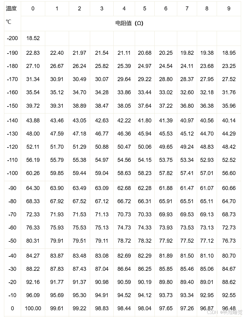
PT100 has a good linear relationship with temperature and is suitable for medium and low temperature temperature measurement. The resistance value of PT100 at different temperatures has a one-to-one corresponding measurement scale as shown in the figure below, which can intuitively display the corresponding relationship between different temperatures and the resistance value of PT100.
The temperature can be known by checking the corresponding resistance value through the PT100 scale.
Pt100 thermal resistor scale
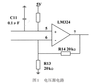
The PT100 temperature measuring device designed in this paper uses the commonly used low-cost four-way operational amplifier LM324 to complete the design of the device power supply circuit and three-op-amp instrument amplifier circuit.
1.1 Voltage source circuit
The circuit in Figure 1 is a common proportional operational circuit. According to the analysis of the ideal operational amplifier working in the linear region, according to the principle of virtual short and virtual break, it is obtained:
, then the closed-loop voltage amplification factor is 2 krat, and then V= 10V is obtained, and it is used as the stable power supply voltage of the Wheatstone bridge circuit.
1.2 Three-wire connection of Wheatstone bridge and PT100.
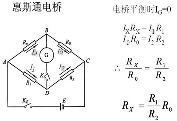
The above figure is a Wheatstone bridge. The condition for the bridge to be balanced is that the potentials of points B and D are equal. So when the bridge is balanced, as long as R1, R2 (usually fixed values) and R0 (usually adjustable values) are read, the resistance Rx to be measured can be obtained. R1/R2=M, klical “multiplier”.
According to the PT100 temperature measurement principle, the resistance value of PT100 needs to be known correctly, but the resistance value cannot be measured directly, so a conversion circuit is required. The resistance value is converted into a voltage signal that can be detected by the microcontroller”. The Wheatstone bridge circuit is an instrument that can correctly measure resistance. As shown in Figure 2, R1, R2, R3, and R4 are its bridge arms respectively. When the bridge is balanced, R1xR3=R2xR4 is satisfied. When the bridge is unbalanced, there will be a voltage difference between points a and b. According to the voltage of points a and b, the corresponding resistance can be calculated. This is the principle of measuring resistance with an unbalanced bridge:
Pravzaprav, due to the small resistance and high sensitivity of PT100, the resistance of the lead wire will cause errors. Zato, the three-wire connection method is often used in industry to eliminate this error. As shown in the dotted part of Figure 2, the lead wire resistance value is equal and is r. V tem času, the bridge arms become R, R, R+2r, and Rt+2r. When the bridge is balanced: R2. (R1+2r) =R1.(R3+2r), sorted out: Rt= R1R3/ R2+2 R1r/ R2- 2r. Analysis shows that when R1=R2, the change in wire resistance has no effect on the measurement result.
1.3 Three-op-amp instrumentation amplifier circuit
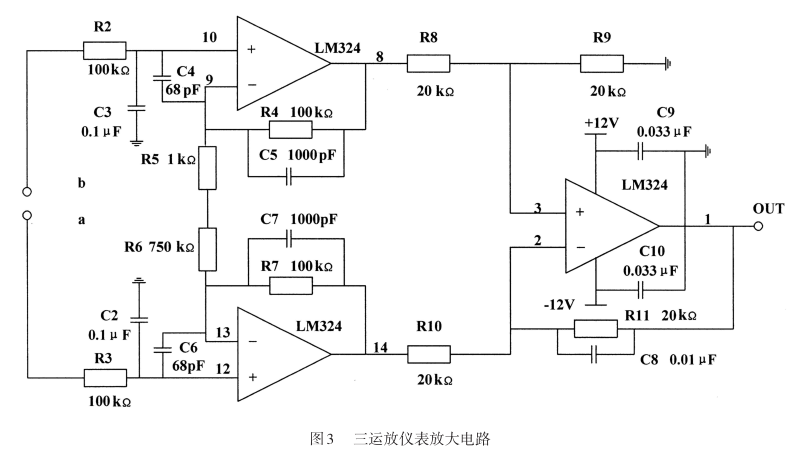
When the temperature changes from 0℃~100℃, the resistance of PT100 changes approximately linearly in the range of 100Ω~138.51Ω. According to the above bridge circuit, the bridge is balanced at 0℃, so the theoretical value of the bridge output voltage should be 0 V, and when the temperature is 100℃, the bridge output is: Uab=U7x(R1/(R1+ R2)-R3/(R2 + R3)), to je, Uab=10x(138.51/(10000 + 138.51)-100/(10000 + 100)) =0.037599V. Since this is a millivolt signal, it is necessary to amplify this voltage to make it detectable by the AD chip.
As shown in Figure 3, the instrumentation amplifier is a device that amplifies small signals in a noisy environment. It has a series of advantages such as low drift, low power consumption, high common-mode rejection ratio, wide power supply range and small size. It uses the characteristics of differential small signals superimposed on larger common-mode signals, which can remove common-mode signals and amplify differential signals at the same time. The output voltage of the standard three-op-amp instrumentation amplifier circuit is, here R8=R10 =20 kΩ, R9=R11=20 kΩ, R4=R7=100kΩ, which can amplify the input voltage signal by about 150 krat, so that the theoretical output voltage of the bridge can be amplified to 0 ~2.34 V. But this is only a theoretical value. In the actual process, there are many factors that can cause resistance changes. Zato, R3 can be replaced with a precision adjustable resistor to facilitate circuit zeroing.
2. Software Design
2.1 Least Squares Method and PT100 Linear Fitting
In the temperature range of 0℃≤t≤850℃, the relationship between Pt100 resistance and temperature is: R=100 (1 +Pri+bt2), where A=3.90802x 10⁻³; B=- -5.80x 10⁻⁷; C=4.2735 x 10⁻¹²
It can be seen that the resistance of PT100 and temperature are not an absolute linear relationship but a parabola. Zato, if t is to be extracted, a square root operation is required, which introduces a more complex function operation and occupies a large amount of CPU resources of the single-chip microcomputer. To solve this problem, we can use the least squares method to linearly fit the relationship between temperature and resistance. ” The least squares curve fitting is a common method for experimental data processing. Its principle is to find a polynomial function to minimize the sum of square errors with the original data.
2.2 AD digital conversion temperature
The PT100 temperature measurement principle is to obtain the temperature value based on its resistance value, so the resistance value of the thermal resistor must be determined first. According to the hardware circuit, the relationship between the output voltage Uab of the bridge circuit and the output voltage Uad of the op amp instrument amplifier circuit is: Uad=Uab. Auf Because the system uses a 12-bit AD chip, the relationship between the digital quantity and the analog quantity is: Uad/AD=5/4096. The relationship between the bridge output voltage and the digital quantity AD can be obtained by combining the previous two equations, to je, Uad/AD=5/(4096Auf). Potem, it is substituted into the bridge output voltage expression Uab= U7x (Rt/ (R1+Rt) -R3/ (R2+R3) ), and the expression of Rr and the digital quantity AD can be obtained. The solution is:
After knowing the resistance value of PT100, the corresponding temperature value can be obtained according to the linear fitting equation in Section 2.1.
2.3 Single-chip digital filtering
In order to improve the temperature measurement accuracy of PT100, a digital filtering program can be added in the software programming, which does not require the addition of hardware circuits and can improve the stability and reliability of the system. There are many filtering methods in the single-chip microcomputer application system. When making a specific selection, the advantages and disadvantages of the filtering method and the applicable objects should be analyzed and compared, so as to select the appropriate filtering method. The algorithm of the median average filtering method is to first continuously collect N data, then remove a minimum value and a maximum value, and finally calculate the arithmetic mean of the remaining data. This filtering method is suitable for measuring parameters that change slowly, such as temperature, and can effectively reduce the interference caused by fluctuations caused by accidental factors or errors caused by sampler instability.
System working process:
When the temperature of the object being measured changes, the resistance of PT100 changes, and the Wheatstone bridge will output a corresponding voltage signal. This signal is a function of the resistance of PT100. This millivolt signal is amplified by a three-op-amp instrumentation amplifier and sent to the AD chip, which converts the analog quantity into a digital quantity and is read by the microcontroller. The microcontroller reads the chip from the AD chip and executes the filtering program, converting the stable digital quantity into the resistance of PT100 through calculation. Then the microcontroller will select the corresponding fitted linear model according to the size of the resistance value to calculate the current temperature value, and finally display the temperature data on the LCD display.
 English
 العربية
 Български
 粤语
粤语 中文(简体)
 中文(漢字)
 Nederlands
 Suomi
Suomi Français
 Deutsch
 Ελληνικά
 Magyar
 Italiano
 日本語
日本語 한국어
한국어 Polski
 Português
 Română
 Русский
 Slovenščina
 Español
 Svenska
 ภาษาไทย
 Türkçe
 Tiếng Việt


