DS18B20 Temperatursensor Kunskap Introduktion
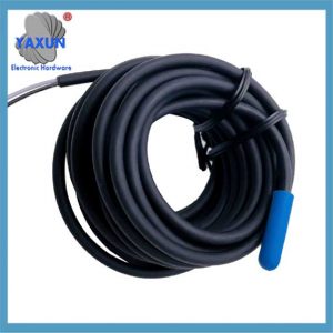
DS18B20 är en vanligt förekommande digital temperatursensor. Det matar ut digitala signaler, har egenskaperna hos liten storlek, låg hårdvaruoverhead, stark anti-interferensförmåga, hög precision, och används allmänt.
Introduktion till DS18B20 temperatursensor
Tekniska funktioner:
①. Unikt gränssnittsläge. När DS18B20 är ansluten till en mikroprocessor, endast 1 Tråd behövs för att realisera tvåvägskommunikation mellan mikroprocessorn och DS18B20.
②. Temperaturmätningsområde -55 ℃~+125 ℃, Inneboende temperaturmätningsfel 1 ℃.
③. Support Multi-Point Networking Function. Flera DS18B20 kan anslutas parallellt på de enda tre ledningarna, och högst maximalt 8 kan anslutas parallellt för att inse mätning av multi-punktstemperatur. Om numret är för stort, strömförsörjningsspänningen blir för låg, vilket resulterar i instabil signalöverföring.
④. Arbetskraftsförsörjning: 3.0~ 5,5V/DC (Parasitisk strömförsörjning kan användas).
⑤. Inga perifera komponenter krävs under användning.
⑥. Mätresultaten överförs seriellt i 9 ~ 12-bitars digital form.
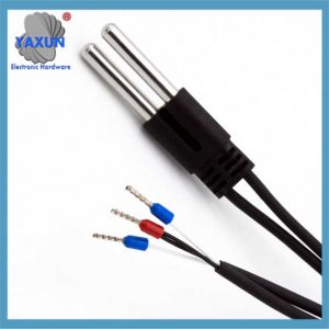
⑦. Diametern på rostfritt stålskyddsrör är φ6.
⑧. Det är lämpligt för temperaturmätning av olika medelstora industriella rörledningar av DN15 ~ 25, DN40 ~ DN250 och utrustning i smala utrymmen.
⑨. Standardinstallationstrådar M10X1, M12X1.5, G1/2 ”är valfria.
⑩. PVC-kabel är direkt ansluten eller tysk bolltypskoppling är ansluten, vilket är bekvämt för anslutning till annan elektrisk utrustning.
DS18B20 Läs och skriv tidpunkt och temperaturmätningsprincip:
DS18B20 Temperaturmätningsprincip visas i figuren 1. Svängningsfrekvensen för den låga temperaturkoefficientkristalloscillatorn i figuren påverkas lite av temperaturen, och används för att generera en fast frekvenspulssignal som ska skickas för att motverka 1. Ovängningsfrekvensen för den höga temperaturkoefficientens kristalloscillator förändras avsevärt med temperaturen, och den genererade signalen används som pulsingång för räknaren 2. Disk 1 och temperaturregistret är förinställt till ett basvärde som motsvarar -55 ℃. Disk 1 Subtrakten Pulssignalen som genereras av den låga temperaturkoefficienten Crystal Oscillator. När det förinställda värdet på räknaren 1 reduceras till 0, värdet på temperaturregistret kommer att ökas med 1, och förinställningen 1 kommer att laddas om. Disk 1 startar om för att räkna pulssignalen som genereras av den låga temperaturkoefficientens kristalloscillator, och cykeln fortsätter tills räknaren 2 räknas till 0, stoppa ansamlingen av temperaturregistret. Just nu, värdet i temperaturregistret är den uppmätta temperaturen. Lutningsackumulatorn används för att kompensera och korrigera olinjäriteten i temperaturmätningsprocessen, och dess utgång används för att korrigera det förinställda värdet på räknaren 1.
Figur 1 är som följer:
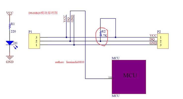
2. DS18B20 och MCU -anslutningsdiagram
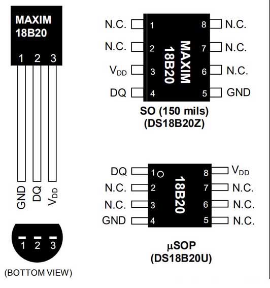
3. DS18B20 -stiftdefinition:
DQ: Datainmatning/utgång. Öppna avtappning 1-trådsgränssnitt. Det kan också ge kraft till enheten när den används i parasitiska kraftläge VDD: Positiv strömförsörjning GND: kraftplats 4. DS18B20 internal analysis introduction:
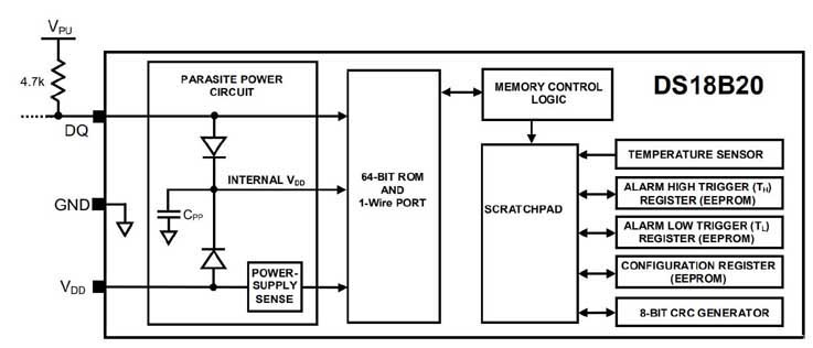
The above figure shows the block diagram of DS18B20, and the 64-bit ROM stores the unique serial code of the device. The buffer memory contains 2 bytes of temperature registers that store the digital output of the temperature sensor. Dessutom, the buffer memory provides access to 1-byte upper and lower alarm trigger registers (TH and TL) and 1-byte configuration registers. The configuration register allows the user to set the resolution of the temperature to digital conversion to 9, 10, 11, eller 12 bits. TH, TL, and configuration registers are non-volatile (EEPROM), so they will retain data when the device is powered off. DS18B20 uses Maxim’s unique 1-wire bus protocol, which uses a control signal. Kontrolllinjen kräver ett svagt pull-up-motstånd eftersom alla enheter är anslutna till bussen genom en 3-statlig eller öppen dräneringsport (DQ -stift i fallet med DS18B20). I detta bussystem (bemästra) använder en unik 64-bitars kod för varje enhet. Eftersom varje enhet har en unik kod, Antalet enheter som kan hanteras på en buss är praktiskt taget obegränsat.
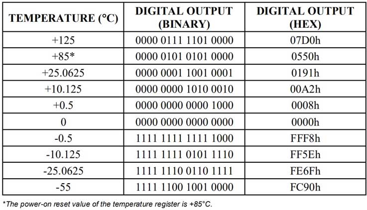
Temperaturregisterformat
Temperatur/dataförhållande
Operationlarmsignal
Efter DS18B20 utför en temperaturomvandling, Det jämför temperaturvärdet med den användardefinierade två komplementalarmutlösningsvärdet lagrat i 1-byte th- och TL-register. Tecknet indikerar om värdet är positivt eller negativt: positiv s = 0, negativ s = 1. The TH and TL registers are non-volatile (EEPROM) and therefore are not volatile when the device is powered off. TH and TL can be accessed through bytes 2 och 3 of the memory.
TH and TL register format:
Schematic diagram of powering the DS18B20 using an external power supply
64-bit laser read-only memory code:
Each DS18B20 contains a unique 64-bit code stored in ROM. The least significant 8 bits of the ROM code contain the single-wire family code of the DS18B20: 28h. The next 48 bits contain a unique serial number. The most significant 8 bits contain a cyclic redundancy check (CRC) byte, which is calculated from the first 56 bits of the ROM code.
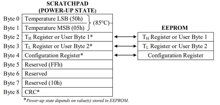
DS18B20 memory map
Configuration Register:
Figur 2
Byte 4 of the memory contains the configuration register, which is organized as shown in Figure 2. The user can set the conversion resolution of the DS18B20 using bits R0 and R1 here as shown in Table 2. The power-on defaults for these bits are R0 = 1 and R1 = 1 (12-bit resolution). Note that there is a direct relationship between resolution and conversion time. Bit 7 and bits 0 till 4 in the configuration register are reserved for internal use of the device and cannot be overwritten.
Tabell 2 Thermometer Resolution Configuration
CRC Generation
The CRC byte is part of the DS18B20 64-bit ROM code and is provided in the 9th byte of the scratchpad. The ROM code CRC is calculated from the first 56 bits of the ROM code and is contained in the most significant byte of the ROM. The scratchpad CRC is calculated based on the data stored in the scratchpad, so it changes when the data in the scratchpad changes. The CRC provides the bus host with a method of data verification when reading data from the DS18B20. After verifying that the data has been read correctly, the bus master must recalculate the CRC from the received data and then compare that value to the ROM code CRC (for ROM reads) or the scratchpad CRC (for scratchpad reads). If the calculated CRC matches the read CRC, the data has been received correctly. The decision to compare the CRC values and proceed is entirely at the bus master’s discretion. There is no circuitry inside the DS18B20 that will prevent the execution of a command sequence if:
The DS18B20 CRC (ROM or scratchpad) Matchar inte värdet som genereras av bussmästaren.
Den motsvarande polynomfunktionen för CRC är:
CRC = x8 + X5 + X4 + 1
Bussmästaren kan beräkna CRC och jämföra den med DS18B20: s CRC -värde med:
Polynomgeneratorn visas i figur 3. Kretsen innehåller ett skiftregister och Yihuo Gates, och bitarna i skiftregistret initialiseras till 0. Den minst betydande biten av ROM -koden eller den minst betydande biten av byte 0 i skrapplattan bör flyttas till skiftregistret en åt gången. Efter att ha växt in bit 56 från rom eller den mest betydande biten av byte 7 från skrapplattan, Polynomgeneratorn kommer att innehålla den omberäknade CRC. Nästa, 8-bitars ROM-koden eller CRC-signalen i skrappaden DS18B20 måste flyttas in i kretsen. Just nu, if the recalculated CRC is correct, the shift register will be all 0s.
Figur 3: CRC Generator
V. Accessing the DS18B20:
The sequence for accessing the DS18B20 is as follows:
Steg 1. Initialization;
Steg 2. ROM command (followed by any necessary data exchange);
Steg 3. DS18B20 function command (followed by any necessary data exchange);
Notera: This sequence is followed every time the DS18B20 is accessed, because the DS18B20 will not respond if any step in the sequence is missing or out of order. The exception to this rule is the Search ROM [F0h] and Alarm Search [ECh] commands. After issuing these two ROM commands, the host must return to step 1 in sequence.
(The above introduction is translated from the official manual)
ROM Command
1, Read ROM [33h]
2, Match ROM [55h]
3, Skip ROM [CCh]
4, Alarm Search [ECh]
DS18B20 Function Command
1, Convert Temperature [44h]
2, Write Scratchpad (Memory) [4Eh]
3, Read Scratchpad (Memory) [BEh]
4, Copy Scratchpad (Memory [48h]
5, Re-wake E2 [B8h]
6, Read Power [B4h]
(For detailed description of the above commands, see the official manual)
Vi. Access DS18B20 Timing
During the initialization process, the bus master sends a reset pulse (TX) low level for at least 480µs by pulling the 1-Wire bus. Then, the bus master releases the bus and enters the receiving mode (RX). After releasing the bus, the 5kΩ pull-up resistor pulls the 1-Wire bus high. When the DS18B20 detects this rising edge, it waits 15µs to 60µs and then sends a presence pulse by pulling the 1-Wire bus low for 60µs to 240µs.
Initialization Timing:
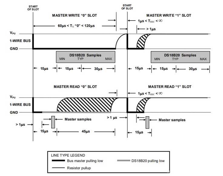
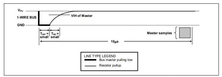
There are two types of write time slots: “Write 1” time slots and “Write 0” time slots. The bus uses a Write 1 time slot to write a logic 1 to the DS18B20 and a Write 0 time slot to write a logic 0 to the DS18B20. All write time slots must be at least 60µs in duration with a recovery time of at least 1µs between individual write time slots. Both types of write time slots are initiated by the master pulling the 1-Wire bus low (see Figure 14). To generate a Write 1 time slot, after pulling the 1-Wire bus low, the bus master must release the 1-Wire bus within 15µs. After releasing the bus, the 5kΩ pull-up resistor pulls the bus high. Generate a
Write 0 time slot, after pulling the 1-Wire line low, the bus master must continue to hold the bus low for the duration of the time slot (at least 60µs). The DS18B20 samples the 1-Wire bus within a window of 15µs to 60µs after the master initiates the write time slot. If the bus is high during the sampling window, a 1 is written to the DS18B20. If the line is low, a 0 is written to the DS18B20.
Notera: Timeslot is a portion of the serial self-multiplexing of the time slot information dedicated to a single channel.
Figur 14 är som följer:
Read time slot:
The DS18B20 can only send data to the host when the host issues a read time slot. Därför, the host must generate a read time slot immediately after issuing a Read Memory Command [BEh] or a Read Power Supply [B4h] command in order for the DS18B20 to provide the required data. Alternatively, the host can generate a read time slot after issuing a Convert T [44h] or Recall E2 [B8h] command to find out the status. All read time slots must be at least 60µs in duration with a minimum recovery time of 1µs between time slots. A read time slot is initiated by the master pulling the 1-Wire bus low to hold it low for at least 1µs and then releasing the bus (see Figure 14). After the master initiates a read time slot, the DS18B20 will begin sending either 1s or 0s on the bus. The DS18B20 sends a 1 by holding the bus high and sends a 0 by pulling the bus low. When a 0 is sent, the DS18B20 releases the bus by holding the bus high. The time slot ends and the bus is pulled back to the high idle state by the pull-up resistor.
 English
 العربية
 Български
 粤语
粤语 中文(简体)
 中文(漢字)
 Nederlands
 Suomi
Suomi Français
 Deutsch
 Ελληνικά
 Magyar
 Italiano
 日本語
日本語 한국어
한국어 Polski
 Português
 Română
 Русский
 Slovenščina
 Español
 Svenska
 ภาษาไทย
 Türkçe
 Tiếng Việt

