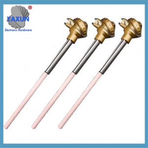
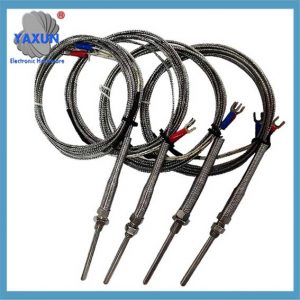
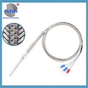
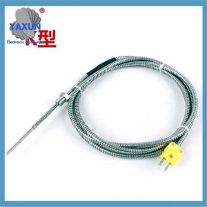
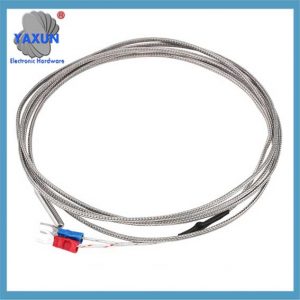
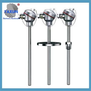
Temperature sensors are widely used and come in many types, but the main common types are: termoelement (PT100/PT1000), termopålar, termistorer, motståndstemperaturdetektorer, och IC temperatursensorer. IC temperature sensors include two types: analog output sensors and digital output sensors. According to the material and electronic component characteristics of the temperature sensor, they are divided into two categories: thermal resistors and thermocouples. Thermocouples have become the industry-standard method for cost-effective measurement of a wide range of temperatures with reasonable accuracy. They are used in a variety of applications up to approximately +2500°C in boilers, varmvattenberedare, ovens, and aircraft engines—to name just a few.
(1) Basic definition of thermocouples
Thermocouples are one of the most commonly used temperature detection elements in industry. The working principle of thermocouples is based on the Seebeck effect, which is a physical phenomenon in which two conductors of different components are connected at both ends to form a loop. If the temperatures of the two connecting ends are different, a thermal current is generated in the loop.
As one of the most widely used temperature sensors in industrial temperature measurement, termoelement, together with platinum thermal resistors, account for about 60% of the total number of temperature sensors. Thermocouples are usually used in conjunction with display instruments to directly measure the surface temperature of liquids, vapors, gaseous media and solids in the range of -40 to 1800°C in various production processes. Advantages include high measurement accuracy, wide measurement range, simple structure and easy use.
(2) Basic principle of thermocouple temperature measurement
Thermocouple is a temperature sensing element that can directly measure temperature and convert it into a thermoelectric potential signal. The signal is converted into the temperature of the measured medium through an electrical instrument. The working principle of the thermocouple is that two conductors of different components form a closed loop. When a temperature gradient exists, current will pass through the loop and generate a thermoelectric potential, which is the Seebeck effect. The two conductors of the thermocouple are called thermocouples, one end of which is the working end (higher temperature) and the other end is the free end (usually at a constant temperature). According to the relationship between thermoelectric potential and temperature, a thermocouple scale is made. Different thermocouples have different scales.
When a third metal material is connected to the thermocouple loop, as long as the temperature of the two contacts of the material is the same, the thermoelectric potential generated by the thermocouple will remain unchanged and will not be affected by the third metal. Därför, when measuring the temperature of the thermocouple, a measuring instrument can be connected to determine the temperature of the measured medium by measuring the thermoelectric potential. Thermocouples weld conductors or semiconductors A and B into a closed loop.
Thermocouples weld two conductors or semiconductors A and B of different materials together to form a closed loop, as shown in the figure.
When there is a temperature difference between the two attachment points 1 och 2 of conductors A and B, an electromotive force is generated between the two, thus forming a current of a certain size in the loop. This phenomenon is called the thermoelectric effect. Thermocouples work by using this effect.
Two conductors of different components (called thermocouple wires or hot electrodes) are connected at both ends to form a loop. When the temperatures of the junctions are different, an electromotive force is generated in the loop. This phenomenon is called the thermoelectric effect, and this electromotive force is called the thermoelectric potential. Thermocouples use this principle to measure temperature. Bland dem, the end directly used to measure the temperature of the medium is called the working end (also called the measuring end), and the other end is called the cold end (also called the compensation end); the cold end is connected to the display instrument or the matching instrument, and the display instrument will indicate the thermoelectric potential generated by the thermocouple.
Thermocouples are energy converters that convert thermal energy into electrical energy and measure the temperature by measuring the generated thermoelectric potential. When studying the thermoelectric potential of thermocouples, the following issues need to be noted:
1) The thermoelectric potential of a thermocouple is a function of the temperature difference between the two ends of the thermocouple, not the temperature difference between the two ends of the thermocouple.
2) The magnitude of the thermoelectric potential generated by a thermocouple has nothing to do with the length and diameter of the thermocouple, but only with the composition of the thermocouple material and the temperature difference between the two ends, provided that the thermocouple material is uniform.
3) After determining the material composition of the two thermocouple wires of the thermocouple, the magnitude of the thermoelectric potential of the thermocouple is only related to the temperature difference of the thermocouple. If the temperature of the cold end of the thermocouple remains constant, the thermoelectric potential of the thermocouple is only a single-valued function of the working end temperature.
Commonly used thermocouple materials are:
(3) Types and structures of thermocouples
Typer
Thermocouples can be divided into two categories: standard thermocouples and non-standard thermocouples. The so-called standard thermocouple refers to a thermocouple whose national standard stipulates the relationship between its thermoelectric potential and temperature, the allowable error, and has a unified standard scale. It has a matching display instrument for selection. Non-standardized thermocouples are inferior to standardized thermocouples in terms of use range or order of magnitude, and generally do not have a unified scale. They are mainly used for measurements in certain special occasions.
Basic structure of thermocouples:
The basic structure of thermocouples used for industrial temperature measurement includes thermocouple wire, insulation tube, protection tube and junction box, etc.
Commonly used thermocouple wires and their properties:
A. Platinum-rhodium 10-platinum thermocouple (with a graduation number of S, also known as single platinum-rhodium thermocouple). The positive electrode of this thermocouple is a platinum-rhodium alloy containing 10% rhodium, and the negative electrode is pure platinum;
Funktioner:
(1) Stable thermoelectric performance, strong oxidation resistance, suitable for continuous use in an oxidizing atmosphere, long-term use temperature can reach 1300℃, when it exceeds 1400℃, even in air, pure platinum wire will recrystallize, making the grains coarse and broken;
(2) Hög precision. It is the highest accuracy grade among all thermocouples and is usually used as a standard or to measure higher temperatures;
(3) Wide range of use, good uniformity and interchangeability;
(4) The main disadvantages are: small differential thermoelectric potential, so low sensitivity; expensive price, low mechanical strength, not suitable for use in a reducing atmosphere or under conditions of metal vapor.
B. Platinum-rhodium 13-platinum thermocouple (with a graduation number of R, also known as single platinum-rhodium thermocouple) The positive electrode of this thermocouple is a platinum-rhodium alloy containing 13%, and the negative electrode is pure platinum. Compared with the S type, its potential rate is about 15% higher. Other properties are almost the same. This type of thermocouple is most used as a high-temperature thermocouple in the Japanese industry, but it is less used in China;
C. Platinum-rhodium 30-platinum-rhodium 6 termoelement (division number B, also known as double platinum-rhodium thermocouple) The positive electrode of this thermocouple is a platinum-rhodium alloy containing 30% rhodium, and the negative electrode is a platinum-rhodium alloy containing 6% rhodium. At room temperature, its thermoelectric potential is very small, so compensation wires are generally not used during measurement, and the influence of cold end temperature changes can be ignored. The long-term use temperature is 1600℃, and the short-term use temperature is 1800℃. Because the thermoelectric potential is small, a display instrument with higher sensitivity is required.
Type B thermocouples are suitable for use in oxidizing or neutral atmospheres, and can also be used for short-term use in vacuum atmospheres. Even in a reducing atmosphere, its life is 10 till 20 times that of Type B. gånger. Since its electrodes are made of platinum-rhodium alloy, it does not have all the disadvantages of the negative electrode of platinum-rhodium-platinum thermocouple. There is little tendency of large crystallization at high temperature, and it has greater mechanical strength. Samtidigt, since it has less influence on the absorption of impurities or the migration of rhodium, its thermoelectric potential does not change seriously after long-term use. The disadvantage is that it is expensive (relative to single platinum-rhodium).
D. Nickel-chromium-nickel-silicon (nickel-aluminum) termoelement (grading number is K) The positive electrode of this thermocouple is a nickel-chromium alloy containing 10% chromium, and the negative electrode is a nickel-silicon alloy containing 3% kisel (the negative electrode of products in some countries is pure nickel). It can measure the medium temperature of 0-1300℃ and is suitable for continuous use in oxidizing and inert gases. The short-term use temperature is 1200℃, and the long-term use temperature is 1000℃. Its thermoelectric potential is The temperature relationship is approximately linear, the price is cheap, and it is the most widely used thermocouple at present.
K-type thermocouple is a base metal thermocouple with strong oxidation resistance. It is not suitable for bare wire use in vacuum, sulfur-containing, carbon-containing atmosphere, and redox alternating atmosphere. When the oxygen partial pressure is low, the chromium in the nickel-chromium electrode will be preferentially oxidized, causing a large change in the thermoelectric potential, but the metal gas has little effect on it. Därför, metal protective tubes are often used.
Disadvantages of K-type thermocouples:
(1) The high-temperature stability of thermoelectric potential is worse than that of N-type thermocouples and precious metal thermocouples. At higher temperatures (till exempel, over 1000°C), it is often damaged by oxidation.
(2) The short-term thermal cycle stability is poor in the range of 250-500°C, som är, at the same temperature point, the thermoelectric potential readings are different during the heating and cooling process, and the difference can reach 2-3°C.
(3) The negative electrode undergoes a magnetic transformation in the range of 150-200°C, causing the graduation value in the range of room temperature to 230°C to deviate from the graduation table. In particular, when used in a magnetic field, thermoelectric potential interference that is independent of time often occurs.
(4) When exposed to high-flux medium-system irradiation for a long time, the elements such as manganese (Mn) och kobolt (Co) in the negative electrode undergo a transformation, making its stability poor, resulting in a large change in thermoelectric potential.
E. Nickel-chromium-silicon-nickel-silicon thermocouple (N) The main features of this thermocouple are: strong temperature control and oxidation resistance below 1300℃, good long-term stability and short-term thermal cycle reproducibility, good resistance to nuclear radiation and low temperature. Dessutom, in the range of 400-1300℃, the linearity of the thermoelectric characteristics of the N-type thermocouple is better than that of the K-type. Dock, the nonlinear error is large in the low temperature range (-200-400℃), and the material is hard and difficult to process.
E. Copper-copper-nickel thermocouple (T) T-type thermocouple, the positive electrode of this thermocouple is pure copper, and the negative electrode is copper-nickel alloy (also known as constantan). Its main features are: among the base metal thermocouples, it has the highest accuracy and good uniformity of the thermoelectrode. Its operating temperature is -200~350℃. Because the copper thermocouple is easy to oxidize and the oxide film is easy to fall off, it is generally not allowed to exceed 300℃ when used in an oxidizing atmosphere, and is within the range of -200~300℃. They are relatively sensitive. Another feature of copper-constantan thermocouples is that they are cheap, and they are the cheapest of several commonly used standardized products.
F. Iron-constantan thermocouple (grading number is J)
J-type thermocouple, the positive electrode of this thermocouple is pure iron, and the negative electrode is constantan (copper-nickel alloy), which is characterized by its cheap price. It is suitable for reducing or inert atmosphere of vacuum oxidation, and the temperature range is from -200~800℃. Dock, the commonly used temperature is only below 500℃, because after exceeding this temperature, the oxidation rate of the iron thermocouple accelerates. If a thick wire diameter is used, it can still be used at high temperature and has a longer life. This thermocouple is resistant to corrosion by hydrogen (H2) and carbon monoxide (CO) gases, but cannot be used in high temperature (till exempel. 500℃) sulfur (S) atmospheres.
G. Nickel-chromium-copper-nickel (Constantan) termoelement (division code E)
Type E thermocouple is a relatively new product, with a positive electrode of nickel-chromium alloy and a negative electrode of copper-nickel alloy (Constantan). Its biggest feature is that among the commonly used thermocouples, its thermoelectric potential is the largest, som är, its sensitivity is the highest. Although its application range is not as wide as that of Type K, it is often selected under conditions that require high sensitivity, low thermal conductivity, and allowable large resistance. The restrictions in use are the same as those of Type K, but it is not very sensitive to corrosion in atmospheres containing high humidity.
In addition to the above 8 commonly used thermocouples, there are also tungsten-rhenium thermocouples, platinum-rhodium thermocouples, iridium-germanium thermocouples, platinum-molybdenum thermocouples, and non-metallic material thermocouples as non-standardized thermocouples. The following table lists the relationship between the material specifications and wire diameter of commonly used thermocouples and the use temperature:
Thermocouple Grading Number Wire Diameter (mm) Long-term Short-term
SΦ0.513001600
RΦ0.513001600
BΦ0.516001800
KΦ1.28001000
(4) Temperature compensation of the cold end of the thermocouple
In order to save the cost of thermocouple materials, especially when using precious metals, a compensation wire is usually used to extend the cold end (free end) of the thermocouple into the control room where the temperature is relatively stable and connect it to the instrument terminal. It should be clear that the role of the thermocouple compensation wire is limited to extending the thermocouple and moving the cold end of the thermocouple to the instrument terminal in the control room. It itself cannot eliminate the influence of the cold end temperature change on the temperature measurement and cannot play a compensation role.
Insulating tube
The working ends of the thermocouple are firmly welded together, and the thermocouples need to be protected by insulating tubes. There are many materials available for insulating tubes, which are mainly divided into organic and inorganic insulation. For the high temperature end, inorganic materials must be selected as insulating tubes. I allmänhet, clay insulating tubes can be selected below 1000℃, high aluminum tubes can be selected below 1300℃, and corundum tubes can be selected below 1600℃.
Protective tube
The function of the protective tube is to prevent the thermocouple electrode from direct contact with the measured medium. Its function not only prolongs the life of the thermocouple, but also provides the function of supporting and fixing the thermoelectrode and enhancing its strength. Därför, the correct selection of thermocouple protection tubes and insulating materials is crucial to the service life and measurement accuracy of the thermocouple. The materials of the protective tube are mainly divided into two categories: metal and non-metal.
Sammanfattning:
Thermocouples are commonly used sensors in industrial temperature measurement, which are characterized by high accuracy, economy and applicability to a wide temperature range. It measures by measuring the temperature difference between the hot end and the cold end.
In order to obtain the temperature of the hot end sensing point, it is necessary to measure the cold end temperature and adjust the output of the thermocouple accordingly. Typically, the cold junction is kept at the same temperature as the input of the thermocouple signal processing unit through a sheet of material with high thermal conductivity. Copper is a material with ideal thermal conductivity (381W/mK). The input connection needs to be electrically isolated to prevent the thermocouple signal from interfering with the heat conduction on the chip. The entire signal processing unit is preferably in this isothermal environment.
The signal range of the thermocouple is usually in the microvolt/℃ level. The thermocouple signal processing unit is very sensitive to electromagnetic interference (EMI), and the thermocouple line is often interfered by EMI. EMI increases the uncertainty of the received signal and damages the accuracy of the collected temperature data. Dessutom, the dedicated thermocouple cable required for the connection is also expensive, and if other types of cables are not carefully substituted, it may cause difficulties in analysis.
Since EMI is proportional to the length of the line, the usual options to minimize interference are to place the control circuit close to the sensing point, add a remote board close to the sensing point, or use complex signal filtering and cable shielding. A more elegant solution is to digitize the thermocouple output close to the sensing point.
(5) Thermocouple process production flow
Thermocouple production process control includes the following:
1) Wire inspection: check geometric dimensions and thermoelectric potential.
2) Compensation wire inspection: check geometric dimensions and thermoelectric potential.
3) Prepare and inspect components such as plastic sockets, aluminum caps, refractory bases, paper tubes and small paper tubes.
4) Hot end welding: verify the qualified rate of solder joints and the qualified rate of length through the P control chart.
5) Wire annealing: including primary annealing (annealing after alkali washing and acid washing) and secondary annealing (annealing after passing through the U-shaped tube), control annealing temperature and time.
6) Process inspection: including polarity judgment, loop resistance and appearance quality as well as geometric dimension inspection.
7) Cold end welding: control welding voltage, check solder joint shape and spherical size.
8) Assembly and pouring: assemble as required, including controlling the hot end position and compensation wire distance. Pouring requirements include cement preparation, baking temperature and time, and insulation resistance measurement.
9) Final inspection: Check the geometry, loop resistance, positive and negative polarity and insulation resistance.
(6) Application of thermocouple sensors
Thermocouples are formed by connecting two different conductors together. When the measurement and reference junctions are at different temperatures, the so-called thermoelectromagnetic force (EMF) is generated. Junction purpose The measurement junction is the part of the thermocouple junction that is at the measured temperature.
The reference junction plays the role of maintaining a known temperature or automatically compensating for temperature changes in the thermocouple. In conventional industrial applications, the thermocouple element is usually connected to the connector, while the reference junction is connected to a controlled environment with a relatively stable temperature through an appropriate thermocouple extension wire. The type of junction can be a shell-connected thermocouple junction or an insulated thermocouple junction.
The shell-connected thermocouple junction is connected to the probe wall by a physical connection (welding), and heat is transferred from the outside to the junction through the probe wall to achieve good heat transfer. This type of junction is suitable for measuring the temperature of static or flowing corrosive gases and liquids, as well as some high-pressure applications.
Insulated thermocouples have junctions that are separated from the probe wall and surrounded by a soft powder. Although insulated thermocouples have a slower response than shelled thermocouples, they provide electrical isolation. Insulated thermocouples are recommended for measuring in corrosive environments, where the thermocouple is completely electrically isolated from the surrounding environment by a sheath shield.
Exposed-terminal thermocouples allow the top of the junction to penetrate the surrounding environment. This type of thermocouple provides the best response time, but is only suitable for non-corrosive, non-hazardous, and non-pressurized applications. Response time can be expressed in terms of a time constant, which is defined as the time required for the sensor to change 63.2% from the initial value to the final value in the controlled environment. Exposed-terminal thermocouples have the fastest response speed, and the smaller the probe sheath diameter, the faster the response speed, but the lower the maximum allowable measurement temperature.
Extension-wire thermocouples use extension wire to transfer the reference junction from the thermocouple to a wire at the other end, which is usually located in the controlled environment and has the same temperature-electromagnetic frequency characteristics as the thermocouple. When properly connected, the extension wire transfers the reference connection point to the controlled environment.
 English
 العربية
 Български
 粤语
粤语 中文(简体)
 中文(漢字)
 Nederlands
 Suomi
Suomi Français
 Deutsch
 Ελληνικά
 Magyar
 Italiano
 日本語
日本語 한국어
한국어 Polski
 Português
 Română
 Русский
 Slovenščina
 Español
 Svenska
 ภาษาไทย
 Türkçe
 Tiếng Việt

