Resistance Temperature Detectors or RTDs may be simple types of temperature sensors. These devices work on the principle that the resistance of a metal changes with temperature. Pure metals generally have a positive temperature coefficient of resistance, meaning that their resistance increases as temperature increases. RTDs operate over a wide temperature range of -200 °C ถึง +850 °C and offer high accuracy, เสถียรภาพระยะยาวที่ยอดเยี่ยม, and repeatability.
In this article, we will discuss the trade-offs of using RTDs, the metals used in them, the two types of RTDs, and how RTDs compare to thermocouples.
Before we dive in, let’s take a look at an example application diagram to better understand RTD basics.
RTD Application Diagram Example
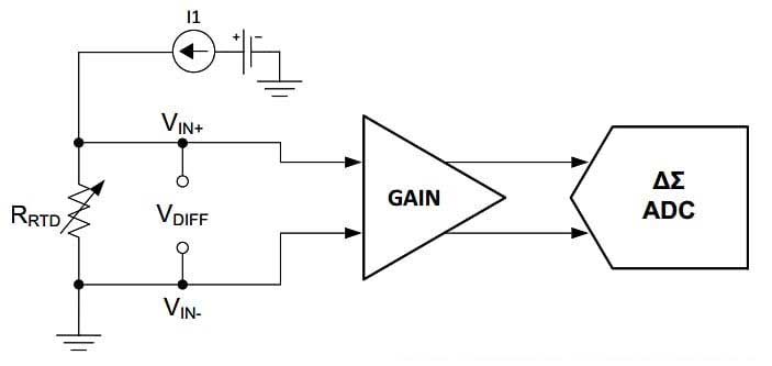
RTDs are passive devices that do not generate an output signal on their own. รูป 1 shows a simplified RTD application diagram.
รูป 1. RTD application diagram example.
The excitation current I1 passes through the temperature-dependent resistance of the sensor. This produces a voltage signal that is proportional to the excitation current and the resistance of the RTD. The voltage across the RTD is then amplified and sent to an ADC (เครื่องแปลงแบบอะนาล็อกเป็นดิจิตอล) to produce a digital output code that can be used to calculate the RTD temperature.
Tradeoffs of Using RTD Sensors – Advantages and Disadvantages of RTD Sensors
Before we dive in, it is important to note that the details of RTD signal conditioning will be covered in a future article. For this article, I want to highlight some basic tradeoffs when using RTD circuits.
อันดับแรก, note that the excitation current is typically limited to around 1 mA to minimize self-heating effects. When the excitation current flows through the RTD, it generates I2R or Joule heating. Self-heating effects can raise the sensor temperature to values above the ambient temperature that is actually being measured. Reducing the excitation current can reduce the self-heating effect. It is also worth mentioning that the self-heating effect depends on the medium in which the RTD is immersed. ตัวอย่างเช่น, an RTD placed in still air may experience more significant self-heating effects than an RTD immersed in flowing water.
For a given detectable temperature change, the change in RTD voltage should be large enough to overcome system noise as well as offsets and drifts of different system parameters. Since self-heating limits the excitation current, we need to use an RTD with a large enough resistance, thus generating a large voltage for the downstream signal processing block. While a large RTD resistance is desirable to reduce measurement errors, we cannot arbitrarily increase the resistance because a larger RTD resistance results in a slower response time.
RTD Metals: Differences Between Platinum, Gold, and Copper RTDs
In theory, any kind of metal can be used to construct an RTD. The first RTD invented by CW Siemens in 1860 used a copper wire. อย่างไรก็ตาม, Siemens soon discovered that platinum RTDs produced more accurate results over a wider temperature range.
วันนี้, platinum RTDs are the most widely used temperature sensors for precision temperature measurement. Platinum has a linear resistance-temperature relationship and is highly repeatable over a large temperature range. นอกจากนี้, platinum does not react with most pollutant gases in the air.
In addition to platinum, two other common RTD materials are nickel and copper. โต๊ะ 1 provides the temperature coefficients and relative conductivity of some common RTD metals.
โต๊ะ 1. Temperature coefficients and relative conductivity of common RTD metals. Data provided by BAPI
| Metals | Relative conductivity (copper = 100% - 20 องศาเซลเซียส) | ค่าสัมประสิทธิ์อุณหภูมิของความต้านทาน |
| Annealed copper | 100% | 0.00393 O/° C |
| Gold | 65% | 0.0034 O/° C |
| Iron | 17.70% | 0.005 O/° C |
| นิกเกิล | 12-16% | 0.006 O/° C |
| แพลตตินัม | 15% | 0.0039 O/° C |
| เงิน | 106% | 0.0038 O/° C |
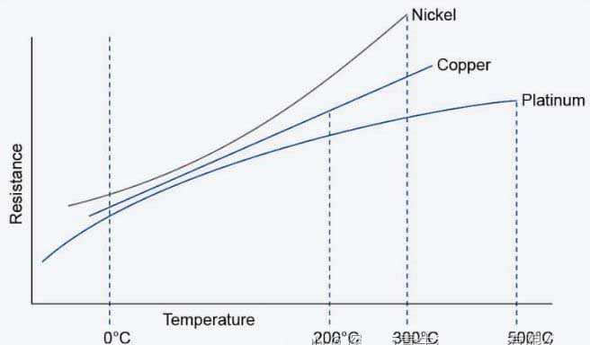
ในส่วนก่อนหน้า, we discussed how larger RTD resistance can reduce measurement errors. Copper has a higher conductivity (or equivalently, lower resistance) than platinum and nickel. For a given sensor size and excitation current, a copper RTD can produce a relatively small voltage. ดังนั้น, copper RTDs can be more challenging to measure small temperature changes. นอกจากนี้, copper oxidizes at higher temperatures, so the measurement range is also limited to -200 ถึง +260 องศาเซลเซียส. Despite these limitations, copper is still used in some applications due to its linearity and low cost. ดังแสดงในรูป 2 below, of the three common RTD metals, copper has the most linear resistance-temperature characteristic.
รูป 2. Resistance vs. temperature characteristics of nickel, ทองแดง, and platinum RTDs. Image courtesy of TE Connectivity
Gold and silver also have relatively low resistance and are rarely used as RTD elements. Nickel has a conductivity close to that of platinum. As can be seen in Figure 2, nickel offers a change in resistance for a given change in temperature.
อย่างไรก็ตาม, nickel offers a lower temperature range, greater nonlinearity, and greater long-term drift than platinum. Additionally, nickel’s resistance varies from batch to batch. Because of these limitations, nickel is used primarily in low-cost applications such as consumer products.
Common platinum RTDs are Pt100 and Pt1000. These names describe the type of metal used in the sensor’s construction (platinum or Pt) and the nominal resistance at 0 องศาเซลเซียส, ซึ่งก็คือ 100 Ω for Pt100 and 1000 Ω for Pt100 and Pt1000 types, ตามลำดับ. Pt100 types were more popular in the past; อย่างไรก็ตาม, today the trend is toward higher resistance RTDs, as higher resistance provides greater sensitivity and resolution at little or no additional cost. RTDs made from copper and nickel use similar naming conventions. โต๊ะ 2 lists some common types.
โต๊ะ 2. RTD types, materials, and temperature ranges. Data provided by Analog Devices
| Thermal resistor type | วัสดุ | พิสัย |
| PT100, พอต1000 | แพลตตินัม (numbers are resistance at 0 องศาเซลเซียส) | -200 °C ถึง +850 องศาเซลเซียส |
| Pt200, ปต500 | แพลตตินัม (numbers are resistance at 0 องศาเซลเซียส) | -200 °C ถึง +850 องศาเซลเซียส |
| Cu10, Cu100 | ทองแดง (numbers are resistance at 0 องศาเซลเซียส) | -100 °C ถึง +260 องศาเซลเซียส |
| นิกเกิล 120 | นิกเกิล (numbers are resistance at 0 องศาเซลเซียส) | -80 °C ถึง +260 องศาเซลเซียส |
In addition to the type of metal used, the mechanical structure of the RTD also affects sensor performance. RTDs can be divided into two basic types: thin film and wirewound. These two types will be discussed in the following sections.
Thin Film vs. Wirewound RTDs
To further our discussion of RTDs, let’s explore two types: thin film and wirewound.
Thin Film RTD Basics
The structure of the thin film type is shown in Figure 3(อัน).
รูป 3. Examples of thin film RTDs, where (อัน) shows the structure and (ข) shows the different overall types. Image (modified) courtesy of Evosensors
In a thin film RTD, a thin layer of platinum is deposited on a ceramic substrate. This is followed by very high temperature annealing and stabilization, and a thin protective glass layer covering the entire element. The trimming area shown in Figure 3(อัน) is used to adjust the manufactured resistance to a specified target value.
Thin film RTDs rely on relatively new technology that significantly reduces assembly time and production costs. Compared to the wirewound type, which we will explore in depth in the next section, thin film RTDs are more resistant to damage from shock or vibration. Additionally, thin-film RTDs can accommodate large resistances in a relatively small area. ตัวอย่างเช่น, อัน 1.6 mm by 2.6 mm sensor provides enough area to produce a resistance of 1000 โอ้. เนื่องจากขนาดเล็กของพวกเขา, thin-film RTDs can respond quickly to temperature changes. These devices are suitable for many general-purpose applications. The disadvantages of this type are relatively poor long-term stability and a narrow temperature range.
Wirewound RTDs
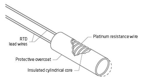
รูป 4. Overview of the construction of a basic wirewound RTD. Image courtesy of PR Electronics
This type of RTD is made by winding a length of platinum around a ceramic or glass core. The entire element is usually encapsulated within a ceramic or glass tube for protection purposes. RTDs with ceramic cores are suitable for measuring very high temperatures. Wirewound RTDs are generally more accurate than thin-film types. อย่างไรก็ตาม, they are more expensive and more easily damaged by vibration.
To minimize any strain on the platinum wire, the thermal expansion coefficient of the material used in the sensor construction should match that of the platinum. Identical thermal expansion coefficients minimize resistance changes caused by long-term stress in the RTD element, thus improving sensor repeatability and stability.
RTD vs. Thermocouple Properties
To wrap up this conversation about RTD temperature sensors, here is a brief comparison between RTD and thermocouple sensors.
A thermocouple produces a voltage that is proportional to the temperature difference between its two junctions. Thermocouples are self-powered and do not require external excitation, whereas RTD-based temperature measurements require an excitation current or voltage. Thermocouple output specifies the temperature difference between the cold and hot junctions, so cold junction compensation is required in thermocouple applications. ในทางกลับกัน, cold junction compensation is not required for RTD applications, resulting in a simpler measurement system.
Thermocouples are typically used in the -184 °C ถึง 2300 °C range, while RTDs can measure from -200 °C ถึง +850 องศาเซลเซียส. Although RTDs are generally more accurate than thermocouples, they are approximately two to three times more expensive than thermocouples. Another difference is that RTDs are more linear than thermocouples and exhibit superior long-term stability. With thermocouples, chemical changes in the sensor material can reduce long-term stability and cause the sensor reading to drift.
 English
 Afrikaans
 العربية
 বাংলা
বাংলা bosanski jezik
 Български
 Català
 粤语
粤语 中文(简体)
 中文(漢字)
 Hrvatski
 Čeština
 Nederlands
 Eesti keel
 Suomi
Suomi Français
 Deutsch
 Ελληνικά
 हिन्दी; हिंदी
 Magyar
 Bahasa Indonesia
 Italiano
 日本語
日本語 한국어
한국어 Latviešu valoda
 Lietuvių kalba
 македонски јазик
 Bahasa Melayu
 Norsk
Norsk پارسی
پارسی Polski
 Português
 Română
 Русский
 Cрпски језик
 Slovenčina
 Slovenščina
 Español
 Svenska
 ภาษาไทย
 Türkçe
 Українська
 اردو
اردو Tiếng Việt
