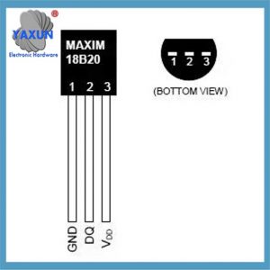
The DS18B20 digital temperature sensor is a one-bus digital temperature sensor produced by DALLAS, USA. It has a wide temperature measurement range (-55℃~+125 ℃) and an inherent temperature measurement resolution of 0.5℃. DS18B20 supports multi-point networking function, and multiple DS18B20 can be connected in parallel on the only three wires to achieve multi-point temperature measurement. The measurement results are transmitted serially in 9~12-bit digital quantity.
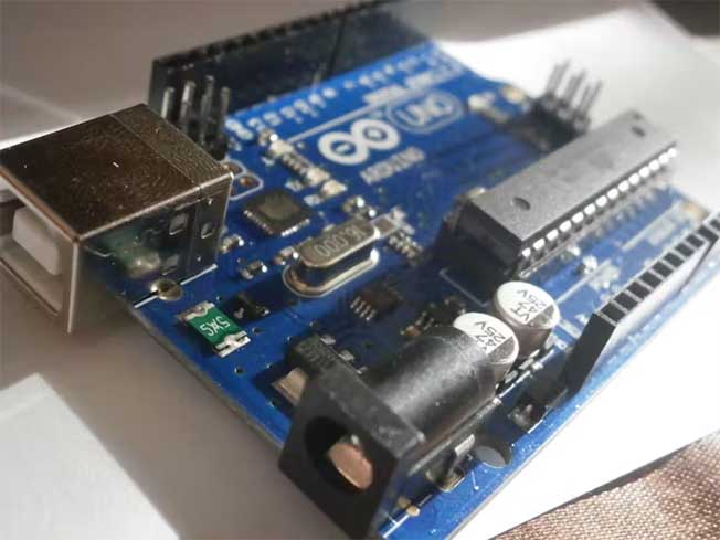
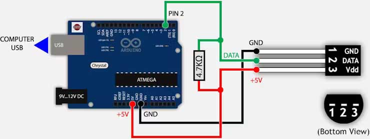
Let’s connect the DS18B20 to the Arduino. The connections are straightforward. Begin by connecting VDD to the Arduino’s 5V pin and GND to ground.
To connect the DS18B20 digital temperature sensor to Arduino, you need to do the following steps:
Hardware connection:
Connect the VCC pin of DS18B20 to the 3.3V power pin of Arduino.
Connect the GND pin of DS18B20 to the ground pin of Arduino.
Connect the data pin of DS18B20 to the GPIO pin of Arduino (Örneğin, GPIO4).
Connect a 4.7kΩ pull-up resistor between the data pin and the 3.3V power pin.
Software Configuration:
Make sure you have installed the Arduino IDE and installed the supporting libraries for the Arduino development board in the IDE.
Write code in the Arduino IDE to read the temperature data from the DS18B20 sensor.
The DS18B20 sensor is unique in that its unique 1-Wire® interface requires only one port pin for communication, and each device has a unique 64-bit serial code stored in the onboard ROM. Ek olarak, it supports power supply via the data line, with a power supply range of 3.0V to 5.5V, making it highly flexible in a variety of applications. Applications for DS18B20 include thermostats, industrial systems, consumer products, thermometers, or any thermal sensitive systems, vesaire
The DS18B20 is a 1-Wire digital temperature sensor from Maxim IC. Reports degrees Celsius from -55 ile 125 (+/-0.5) ile 9 ile 12 digits of accuracy. Each sensor is engraved with a unique 64-bit serial number – allowing a large number of sensors to be used on one data bus.
Özellikler:
Unique 1-Wire® interface requires only one port pin for communication;
Each device has a unique 64-bit serial code stored in onboard ROM;
Multidrop capability simplifies distributed temperature sensing applications;
No external components required;
Can be powered via the data line.
Power supply range is 3.0V to 5.5V;
Measures temperature from –55°C to +125°C (–67°F to +257°F) ±0.5°C Accuracy is –10°C to +85°C;
Thermometer resolution is user selectable from 9 ile 12 bits;
Converts temperature to a 12-bit digital word in 750 milliseconds (maksimum);
User definable nonvolatile (NV) alarm settings;
Alarm search command identifies and addresses devices with temperatures outside programmed limits (temperature alarm condition);
Applications include thermostats, industrial systems, consumer products, thermometers, or any heat sensitive system.
Adım 2: What You Need:
To build the thermometer, you will need the following items:
An Arduino board (UNO, DUE, Mikro, vesaire.).
A waterproof DS18B20 sensor and a 4.7k resistor.
Jumper wires to connect everything together.
Some stores sell sensors with a 4.7k resistor.
Adım 3: Build a simple circuit
To print the data from the DS18B20 on the serial monitor of the IDE, you have to build the circuit as per the schematic.
First plug the sensor into the breadboard and connect its pins to the Arduino using jumpers in the following order: pin 1 to GND; pin 2 to any digital pin (pin 2 in our case); pin 3 to +5V or +3.3V and finally the pull-up resistor.
 English
 العربية
 Български
 粤语
粤语 中文(简体)
 中文(漢字)
 Nederlands
 Suomi
Suomi Français
 Deutsch
 Ελληνικά
 Magyar
 Italiano
 日本語
日本語 한국어
한국어 Polski
 Português
 Română
 Русский
 Slovenščina
 Español
 Svenska
 ภาษาไทย
 Türkçe
 Tiếng Việt


