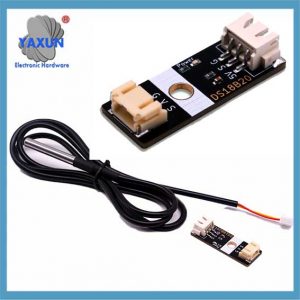
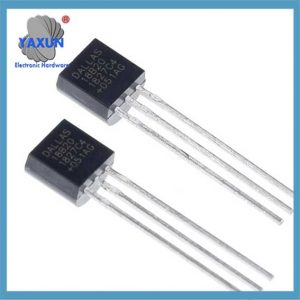
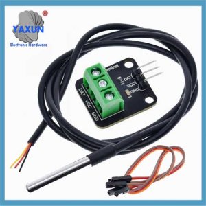
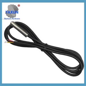
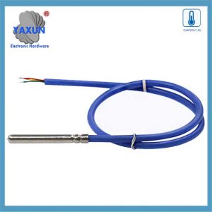
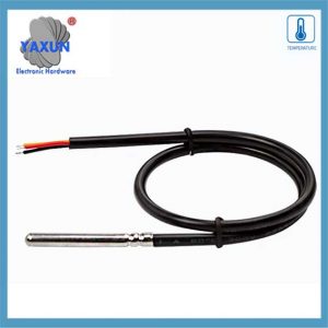
We offer a wide range of the best 1-Wire DS18B20 sensor connectors, including Nanoflex, DisplayPort, USB, Solar, SATA, HDMI, ATA IDE, SAS & many more. All cables are manufactured to the highest industry standards. Using Sensor Circuit Assembly for box builds allows you to focus on your design and marketing, reduce costs, and reap the benefits of our assembly lines, QA processes, and manufacturing expertise.
DS18B20 感測器使用以下方式進行通訊 “1-金屬絲” 協定, 這意味著它使用一條數據線與微控制器進行所有通信, 允許多個感測器連接在同一條線上並透過其唯一的 64 位元串列程式碼進行識別; 此單一數據線透過電阻器拉高,感測器透過在特定時隙期間拉低線來發送訊息位元來傳輸數據.
DS18B20溫度傳感器: The DS18B20 waterproof probe is designed for underwater use, capable of operating in wet or moist environments without being damaged by water or moisture.
Temperature sensor supply voltage: 3.0V ~ 5.25V;
工作溫度範圍:-55 ℃ 至 +125 ℃ (-67 ℉ to +257 ℉);
Provides from 9-bit to 12-bit Celsius temperature measurements;
Adapter module is equipped with a pull-up resistor, and directly connects to the GPIO of the Raspberry Pi without an external resistor;
Use this adapter module kit to simplify connecting the waterproof temperature sensor to your project.
1. Key points about the 1-Wire protocol:
Single data line:
Only one wire is needed for communication between the sensor and the microcontroller.
Half-duplex communication:
Data can be sent in both directions, but only one direction at a time.
Parasite power:
The DS18B20 can be powered directly from the data line during communication, eliminating the need for a separate power supply in some cases.
Unique device addresses:
Each DS18B20 sensor has a unique 64-bit serial code that allows the microcontroller to identify and address individual sensors on the bus.
Communication steps with a DS18B20:
1.1 Reset pulse:
The microcontroller initiates communication by pulling the data line low for a specific duration (重設脈衝).
1.2 Presence pulse:
If a DS18B20 is present on the bus, it will respond with a short pulse, indicating its presence.
1.3 ROM command:
The microcontroller sends a ROM command to either read the unique 64-bit code of a specific sensor (“匹配ROM”) or to address all sensors on the bus (“跳過ROM”).
1.4 Function command:
Depending on the desired operation (like reading temperature), the microcontroller sends a specific function command to the sensor.
1.5 Data transfer:
Data is transmitted bit-by-bit, with the sensor pulling the data line low to send a ‘0’ and letting the line go high to send a ‘1’.
2. DS18B20的1線通信協議的詳細說明
DS18B20傳感器被廣泛使用的原因很大程度上是由於其獨特的通信協議 – 1-電線通信協議. 該協議簡化了硬件連接的要求,並提供了傳輸數據的有效方法. 本章將深入分析1線通信協議的工作機制和數據交換過程,以為後續的編程實踐奠定堅實的基礎.
2.1 1線通信協議的基礎知識
2.1.1 1線通信協議的功能:
DS18B20 1線路通信協議也稱為 “單巴士” 科技. 它具有以下功能: – 單巴士通信: 僅用於雙向數據傳輸, 與傳統的多線傳感器通信方法相比,這大大降低了接線的複雜性. – 多設備連接: 支持在一個數據總線上連接多個設備, 並通過設備識別代碼來識別和通信. – 低功耗: 溝通過程中, 不參與通信時,該設備可以處於低功率待機狀態. – 高精度: 隨著數據傳輸時間較短, 它可以減少外部干擾並提高數據準確性.
2.1.2 1線通信的數據格式和定時分析
1線通信協議的數據格式遵循特定的計時規則. 它包括初始化時間, 寫入時間並閱讀時間安排:
初始化時機: 主機首先開始存在檢測時間 (存在脈衝) 通過將公共汽車拉下一段時間, 然後,傳感器會發出響應的存在脈衝.
寫入時間: 當主機發送寫入時間時, 它首先將公共汽車拉下來 1-15 微秒, 然後釋放公共汽車, 傳感器將公共汽車拉入 60-120 微秒響應.
閱讀時間: 主機通過拉下公共汽車並釋放傳感器通知傳感器發送數據, 傳感器將在一定的延遲後輸出總線上的數據位.
2.2 Software implementation of data communication
2.2.1 Initialization and reset of 1-line communication
At the software level, initialization and reset of 1-Wire communication is the first step of communication. The following is the pseudo code to implement this process:
// OneWire communication initialization function
void OneWire_Init() {
// Set the bus to input mode and enable the pull-up resistor
SetPinMode(DS18B20_PIN, INPUT_PULLUP);
// Wait for the bus to be idle
DelayMicroseconds(1);
// Send a reset pulse
OneWire_Reset();
}
// OneWire communication reset function
void OneWire_Reset() {
// Pull down the bus
SetPinMode(DS18B20_PIN, OUTPUT_LOW);
DelayMicroseconds(480);
// Release the bus
SetPinMode(DS18B20_PIN, INPUT_PULLUP);
DelayMicroseconds(70);
// Wait for the presence of a pulse
如果 (!WaitForOneWirePresence())
// No pulse was detected, maybe the sensor is not connected or the initialization failed
HandleError();
DelayMicroseconds(410);
}
// Waiting for the presence of a pulse
bool WaitForOneWirePresence() {
return ReadPin(DS18B20_PIN) == 0; // Assume low level is a signal presence
}
2.2.2 Data reading and writing operations
Data reading and writing operations are the core part of sensor communication. The following code shows how to write a byte to a one-wire bus:
// Write a byte to a one-wire bus
void OneWire_WriteByte(byte data) {
為了 (int i = 0; 我 < 8; 我++) {
OneWire_WriteBit(數據 & 0x01);
數據 >>= 1;
}
}
// Write a bit to a one-wire bus
void OneWire_WriteBit(bit data) {
SetPinMode(DS18B20_PIN, OUTPUT_LOW);
如果 (數據) {
// Release the bus when writing 1
SetPinMode(DS18B20_PIN, INPUT_PULLUP);
DelayMicroseconds(1);
} 別的 {
// Continue to pull the bus low when writing 0
DelayMicroseconds(60);
}
SetPinMode(DS18B20_PIN, INPUT_PULLUP);
DelayMicroseconds(1);
}
Next is the function to read a byte:
// Read a byte from the one-wire bus
byte OneWire_ReadByte() {
byte data = 0;
為了 (int i = 0; 我 < 8; 我++) {
數據 >>= 1;
如果 (OneWire_ReadBit())
數據 |= 0x80;
}
傳回數據;
}
// Read a bit from the one-wire bus
bit OneWire_ReadBit() {
SetPinMode(DS18B20_PIN, OUTPUT_LOW);
SetPinMode(DS18B20_PIN, INPUT_PULLUP);
DelayMicroseconds(3);
bool result = ReadPin(DS18B20_PIN);
DelayMicroseconds(57);
return result;
}
2.2.3 Verification mechanism of OneWire communication
The OneWire communication protocol uses a simple verification mechanism in the data exchange process, usually by reading back the written data to verify the correctness of the data. The following is a sample code for verifying the written data:
byte data = 0x55; // Assume that the data to be sent
OneWire_WriteByte(數據); // Write data to the OneWire bus
byte readData = OneWire_ReadByte(); // Read back data from the OneWire bus
如果 (readData != data) {
HandleError(); // If the read-back data does not match the written data, handle the error
 English
 Afrikaans
 العربية
 বাংলা
বাংলা bosanski jezik
 Български
 Català
 粤语
粤语 中文(简体)
 中文(漢字)
 Hrvatski
 Čeština
 Nederlands
 Eesti keel
 Suomi
Suomi Français
 Deutsch
 Ελληνικά
 हिन्दी; हिंदी
 Magyar
 Bahasa Indonesia
 Italiano
 日本語
日本語 한국어
한국어 Latviešu valoda
 Lietuvių kalba
 македонски јазик
 Bahasa Melayu
 Norsk
Norsk پارسی
پارسی Polski
 Português
 Română
 Русский
 Cрпски језик
 Slovenčina
 Slovenščina
 Español
 Svenska
 ภาษาไทย
 Türkçe
 Українська
 اردو
اردو Tiếng Việt

