DS18B20是DALLAS公司生產的1線數位溫度感測器, 採用 3 腳 TO-92 小封裝. 溫度測量範圍-55℃~+125℃, 並可編程為9位~12位A/D轉換精度. 測溫分辨率可達0.0625℃, 測量的溫度以帶有符號擴展的16位數字量的形式串行輸出. 其工作電源可從遠端引入或由寄生電源產生. 多個 DS18B20 可以並聯 3 或者 2 線. CPU只需要一根端口線即可與多台DS18B20通信, 佔用微處理器的端口更少, 可以節省大量引線和邏輯電路. 以上特點使得DS18B20非常適合遠距離多點溫度檢測系統.
2. DS18B20內部結構 DS18B20電路圖
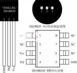
DS18B20內部結構如圖 1, 主要包括 4 部分: 64-位只讀存儲器, 溫度感應器, 非揮發性溫度警報觸發器 TH 和 TL, 和配置寄存器. DS18B20的引腳排列如圖 2. DQ為數位訊號輸入/輸出端; GND是電源地; VDD是外部電源輸入終端 (寄生電源接線方式接地, 見圖 4).
ROM中的64位序列號在出廠前經過光刻. 可以看作是DS18B20的地址序列碼. 每個DS18B20的64位序列號是不同的. 循環冗餘校驗碼 (CRC=X8+X5+X4+1) 64位ROM的排列. ROM的作用是讓每個DS18B20都不同, 這樣多個 DS18B20 就可以連接到一條總線上.
數位 1, DS18B20內部結構
DS18B20中的溫度傳感器完成溫度測量, 以 16 位符號擴展二進制補碼讀數的形式提供, 以0.0625℃/LSB的形式表示, 其中 S 是符號位. 例如, +125℃數位輸出為07D0H, +25.0625℃數位輸出為0191H, -25.0625℃數字輸出為FF6FH, -55℃數位輸出為FC90H.
23
22
21
20
2-1
2-2
2-3
2-4
溫度值低字節
MSBLSB
S
S
S
S
S
22
25
24
溫度值高字節
高低溫報警觸發TH和TL, 和配置寄存器由一個字節的EEPROM組成. 可以使用存儲功能命令寫入TH, TL, 或配置寄存器. 配置寄存器的格式如下:
0
R1
R0
1
1
1
1
1
MSBLSB
R1和R0決定溫度轉換的精度位數: R1R0 = “00”, 9-位精度, 最大轉換時間為 93.75ms; R1R0 = “01”, 10-位精度, 最大轉換時間為 187.5ms. R1R0 = “10”, 11-位精度, 最大轉換時間為 375ms. R1R0 = “11”, 12-位精度, 最大轉換時間為 750ms. 未編程時默認為12位精度.
高速寄存器是9字節存儲器. 前兩個字節包含測量溫度的數字信息; 第三個, 4th, 第 5 個字節是 TH 的臨時副本, TL, 和配置寄存器, 分別, 每次上電複位時都會刷新; 第六號, 7th, 第8個字節未使用,表示為全邏輯1; 第9個字節讀取前面所有的CRC碼 8 位元組, 可用於確保正確的通信.
3. DS18B20工作時序
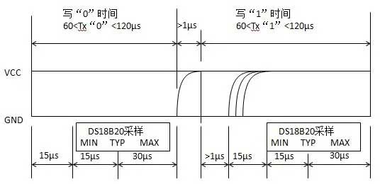
DS18B20的一線工作協議流程為: 初始化→ROM操作指令→存儲器操作指令→數據傳輸. 其工作順序包括初始化順序, 寫入順序和讀取順序, 如圖 3 (一個) (乙) (c).
(一個) 初始化順序
(c) 讀取序列
數位 3, DS18B20工作時序圖
4. DS18B20與單片機的典型接口設計
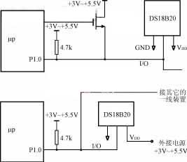
數位 4 以MCS-51系列單片機為例,畫出DS18B20與微處理器的典型連接. 圖中 4 (一個), DS18B20採用寄生供電方式, 其 VDD 和 GND 端子均接地. 圖中 4 (乙), DS18B20採用外部供電方式, 其VDD端採用3V~5.5V電源供電.
一個) 寄生電源工作模式
(乙) 外接電源工作模式
數位 4 DS18B20與微處理器的典型連接圖
假設單片機系統使用的晶振頻率為12MHz, 根據初始化時序編寫三個子程序, DS18B20的寫時序和讀時序: INIT是初始化子程序; WRITE 是寫入 (命令或數據) 子程序; READ 是讀取數據子程序. 所有數據讀寫都是從最低位開始.
數據採集1.0
……
初始化:CLREA
INI10:設定BDAT
MOVR2#200
INI11:克拉達特
DJNZR2、INI11; 主機發送復位脈衝3μs×200=600μs
設定BDAT; 主機釋放總線, 並將端口線更改為輸入
MOVR2#30
IN12:DJNZR2、INI12; DS18B20等待2μs×30=60μs
CLRC
奧爾克,那; DS18B20數據線是否為低電平 (脈衝存在)?
傑西尼10; DS18B20尚未準備好, 重新初始化
MOVR6, #80
INI13: 奧爾克, 那
JCINI14; DS18B20數據線變高, 初始化成功
DJNZR6, INI13; 數據線低電平可持續3μs × 80 = 240μs
辛皮尼10; 初始化失敗, 重新啟動
INI14: 移動VR2, #240
IN15: DJNZR2, INI15; DS18B20 響應時間至少 2μs × 240 = 48 0微秒
視網膜色素變性
;-------------------------
寫:CLREA
MOVR3,#8;環形 8 次, 寫一個字節
WR11:設定BDAT
MOVR4,#8
RRCA;寫位從 A 移至 CY
克拉達特
WR12:DJNZR4、WR12
;等待16μs
移動數據傳輸技術,C;命令字逐位發送到DS18B20
MOVR4#20
WR13:DJNZR4,WR1 3
; 確保寫入過程持續60μs
DJNZR3、WR11
; 發送字節之前繼續
設定BDAT
視網膜色素變性
;------------------------
讀:CLREA
MOVR6,#8; 環形 8 次, 讀取一個字節
RD11:克拉達特
MOVR4,#4
諾普; 低電平持續2μs
設定BDAT; 設置端口線輸入
RD12:DJNZR4,RD12
; 等待8μs
MOVC,從 T
;主機逐位讀取DS18B20的數據
RRCA;讀取的數據移動到A
MOVR5#30
RD13:DJNZR5,RD13
;確保讀取過程持續60μs
DJNZR6、RD11
;讀取一個字節數據後, 將其存儲在A中
設定BDAT
視網膜色素變性
;-------------------------
主機控制DS18B20完成溫度轉換必須經過三步: 初始化, ROM操作說明, 和內存操作指令. 讀取溫度轉換值之前必須先啟動DS18B20開始轉換. 假設一根線上只連接一顆芯片, 使用默認的12位轉換精度, 並且使用外部電源, 可以編寫子程序GETWD來完成轉換並讀取溫度值.
天才:LCallinit
移動,#0CCH
呼叫寫入; 發送跳過 ROM 命令
移動,#44H
呼叫寫入; 發送啟動轉換命令
LCallinit
移動,#0CCH; 發送跳過 ROM 命令
呼叫寫入
移動,#0 貝赫; 發送讀內存命令
呼叫寫入
L呼叫讀取
MOVWDLSB,A
; 將溫度值的低字節發送到WDLSB
L呼叫讀取
MOVWDMSB,A
; 將溫度值的高字節發送到 WDMSB
視網膜色素變性
……
子程序GETWD讀取的溫度值高字節發送到WDMSB單元, 低字節被發送到WDLSB單元. 然後根據溫度值字節及其符號位的表示格式, 通過簡單變換即可得到實際溫度值.
如果一根線上連接多個DS18B20, 採用寄生電源連接方式, 轉換精度配置, 高低限報警, ETC. 是必需的. 那麼子程序GETWD的寫法會比較複雜. 由於空間限制, 本節不再詳細描述. 請參考相關內容.
我們已經成功地將DS18B20應用到 “家用加熱浴缸” 我們開發的控制系統. 其轉換速度快, 轉換精度高, 與微處理器的簡單接口給硬件設計工作帶來了極大的方便, 有效降低成本,縮短開發週期.
 English
 Afrikaans
 العربية
 বাংলা
বাংলা bosanski jezik
 Български
 Català
 粤语
粤语 中文(简体)
 中文(漢字)
 Hrvatski
 Čeština
 Nederlands
 Eesti keel
 Suomi
Suomi Français
 Deutsch
 Ελληνικά
 हिन्दी; हिंदी
 Magyar
 Bahasa Indonesia
 Italiano
 日本語
日本語 한국어
한국어 Latviešu valoda
 Lietuvių kalba
 македонски јазик
 Bahasa Melayu
 Norsk
Norsk پارسی
پارسی Polski
 Português
 Română
 Русский
 Cрпски језик
 Slovenčina
 Slovenščina
 Español
 Svenska
 ภาษาไทย
 Türkçe
 Українська
 اردو
اردو Tiếng Việt


