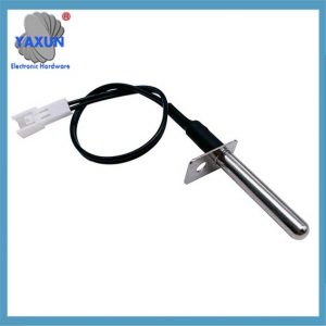
DS18B20是DALLAS公司生产的1线数字温度传感器, 采用 3 引脚 TO-92 小封装. 温度测量范围-55℃~+125℃, 并可编程为9位~12位A/D转换精度. 测温分辨率可达0.0625℃, 测量的温度以带有符号扩展的16位数字量的形式串行输出. 其工作电源可从远端引入或由寄生电源产生. 多个 DS18B20 可以并联 3 或者 2 线. CPU只需要一根端口线即可与多台DS18B20通信, 占用微处理器的端口更少, 可以节省大量引线和逻辑电路. 以上特点使得DS18B20非常适合远距离多点温度检测系统.
2. DS18B20内部结构 DS18B20电路图
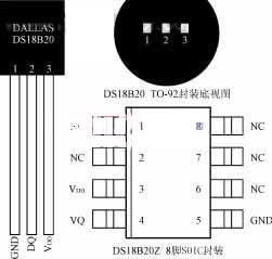
DS18B20内部结构如图 1, 主要包括 4 部分: 64-位只读存储器, 温度传感器, 非易失性温度报警触发器 TH 和 TL, 和配置寄存器. DS18B20的引脚排列如图 2. DQ为数字信号输入/输出端; GND是电源地; VDD为外部电源输入端 (寄生电源接线方式接地, 见图 4).
ROM中的64位序列号在出厂前经过光刻. 可以看作是DS18B20的地址序列码. 每个DS18B20的64位序列号是不同的. 循环冗余校验码 (CRC=X8+X5+X4+1) 64位ROM的排列. ROM的作用是让每个DS18B20都不同, 这样多个 DS18B20 就可以连接到一条总线上.
数字 1, DS18B20内部结构
DS18B20中的温度传感器完成温度测量, 以 16 位符号扩展二进制补码读数的形式提供, 以0.0625℃/LSB的形式表示, 其中 S 是符号位. 例如, +125℃数字输出为07D0H, +25.0625℃数字输出为0191H, -25.0625℃数字输出为FF6FH, -55℃数字输出为FC90H.
23
22
21
20
2-1
2-2
2-3
2-4
温度值低字节
MSBLSB
S
S
S
S
S
22
25
24
温度值高字节
高低温报警触发TH和TL, 和配置寄存器由一个字节的EEPROM组成. 可以使用存储功能命令写入TH, TL, 或配置寄存器. 配置寄存器的格式如下:
0
R1
罗0
1
1
1
1
1
MSBLSB
R1和R0决定温度转换的精度位数: R1R0 = “00”, 9-位精度, 最大转换时间为 93.75ms; R1R0 = “01”, 10-位精度, 最大转换时间为 187.5ms. R1R0 = “10”, 11-位精度, 最大转换时间为 375ms. R1R0 = “11”, 12-位精度, 最大转换时间为 750ms. 未编程时默认为12位精度.
高速寄存器是9字节存储器. 前两个字节包含测量温度的数字信息; 第三个, 4th, 第 5 个字节是 TH 的临时副本, TL, 和配置寄存器, 分别, 每次上电复位时都会刷新; 第六号, 7th, 第8个字节未使用,表示为全逻辑1; 第9个字节读取前面所有的CRC码 8 字节, 可用于确保正确的通信.
3. DS18B20工作时序
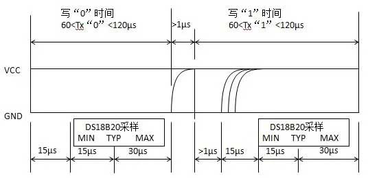
DS18B20的一线工作协议流程为: 初始化→ROM操作指令→存储器操作指令→数据传输. 其工作顺序包括初始化顺序, 写入顺序和读取顺序, 如图 3 (一个) (乙) (c).
(一个) 初始化顺序
(c) 读取序列
数字 3, DS18B20工作时序图
4. DS18B20与单片机的典型接口设计
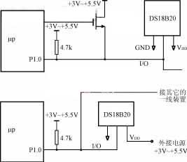
数字 4 以MCS-51系列单片机为例,画出DS18B20与微处理器的典型连接. 图中 4 (一个), DS18B20采用寄生供电方式, 其 VDD 和 GND 端子均接地. 图中 4 (乙), DS18B20采用外部供电方式, 其VDD端采用3V~5.5V电源供电.
一个) 寄生电源工作模式
(乙) 外接电源工作模式
数字 4 DS18B20与微处理器的典型连接图
假设单片机系统使用的晶振频率为12MHz, 根据初始化时序编写三个子程序, DS18B20的写时序和读时序: INIT是初始化子程序; WRITE 是写入 (命令或数据) 子程序; READ 是读取数据子程序. 所有数据读写都是从最低位开始.
数据采集1.0
……
初始化:CLREA
INI10:设定BDAT
MOVR2#200
INI11:CLRDAT
DJNZR2、INI11; 主机发送复位脉冲3μs×200=600μs
设定BDAT; 主机释放总线, 并将端口线更改为输入
MOVR2#30
IN12:DJNZR2、INI12; DS18B20等待2μs×30=60μs
CLRC
有机液相色谱法,那; DS18B20数据线是否为低电平 (脉冲存在)?
杰西尼10; DS18B20尚未准备好, 重新初始化
MOVR6, #80
INI13: 有机液相色谱法, 那
JCINI14; DS18B20数据线变高, 初始化成功
DJNZR6, INI13; 数据线低电平可持续3μs × 80 = 240μs
辛皮尼10; 初始化失败, 重新启动
INI14: 移动VR2, #240
IN15: DJNZR2, INI15; DS18B20 响应时间至少 2μs × 240 = 48 0微秒
视网膜色素变性
;-------------------------
写:CLREA
MOVR3,#8;环形 8 次, 写一个字节
WR11:设定BDAT
MOVR4,#8
RRCA;写位从 A 移至 CY
CLRDAT
WR12:DJNZR4、WR12
;等待16μs
移动数据传输技术,C;命令字逐位发送到DS18B20
MOVR4#20
WR13:DJNZR4,WR1 3
; 确保写入过程持续60μs
DJNZR3、WR11
; 发送字节之前继续
设定BDAT
视网膜色素变性
;------------------------
读:CLREA
MOVR6,#8; 环形 8 次, 读取一个字节
RD11:CLRDAT
MOVR4,#4
诺普; 低电平持续2μs
设定BDAT; 设置端口线输入
RD12:DJNZR4,RD12
; 等待8μs
MOVC,从 T
;主机用位读取DS18B20位的数据
RRCA;读取数据已移至
movr5,#30
RD13:DJNZR5,RD13
;确保阅读过程持续60μs
DJNZR6,RD11
;阅读数据字节后, 将其存储在
设定BDAT
视网膜色素变性
;-------------------------
主机必须经过三个步骤来控制DS18B20才能完成温度转换: 初始化, ROM操作说明, 和内存操作说明. 在阅读温度转换值之前,必须开始开始转换DS18B20. 假设只有一个芯片连接到一条线, 使用默认的12位转换精度, 并使用了外部电源, 可以编写子例程getWD以完成转换并阅读温度值.
天才:lcallinit
Mova,#0CCH
lcallwrite; 发送Skip ROM命令
Mova,#44H
lcallwrite; 发送开始转换命令
lcallinit
Mova,#0CCH; 发送Skip ROM命令
lcallwrite
Mova,#0BH; 发送读取内存命令
lcallwrite
lcallread
movwdlsb,A
; 将温度值的低字节发送至WDLSB
lcallread
movwdmsb,A
; 向WDMSB发送高温度值的高字节
视网膜色素变性
……
subroutine getWD读取的温度值高字节已发送到WDMSB单元, 低字节被发送到WDLSB单元. 然后根据温度值字节的表示格式及其符号位, 可以通过简单的转换获得实际温度值.
如果多个DS18B20连接到一行, 采用寄生电源连接模式, 转换精度配置, 高和低极限警报, ETC. 需要. 那么子例程getwd的写作将更加复杂. 由于空间限制, 本节将不会详细描述. 请参考相关内容.
我们已成功地将DS18B20应用于 “家用加热浴” 我们开发的控制系统. 它的快速转换速度, 高转换精度, 与微处理器的简单界面为硬件设计工作带来了极大的便利, 有效降低成本并缩短发展周期.
 English
 Afrikaans
 العربية
 বাংলা
বাংলা bosanski jezik
 Български
 Català
 粤语
粤语 中文(简体)
 中文(漢字)
 Hrvatski
 Čeština
 Nederlands
 Eesti keel
 Suomi
Suomi Français
 Deutsch
 Ελληνικά
 हिन्दी; हिंदी
 Magyar
 Bahasa Indonesia
 Italiano
 日本語
日本語 한국어
한국어 Latviešu valoda
 Lietuvių kalba
 македонски јазик
 Bahasa Melayu
 Norsk
Norsk پارسی
پارسی Polski
 Português
 Română
 Русский
 Cрпски језик
 Slovenčina
 Slovenščina
 Español
 Svenska
 ภาษาไทย
 Türkçe
 Українська
 اردو
اردو Tiếng Việt


